


 English
LILYGO T-Display S3 AMOLED Plus
Version History:
| Version | Update Date | Update Description |
|---|---|---|
| T-Display-S3-AMOLED-Plus_V1.0 | 2024-01-01 | Initial Version |
Purchase Link
| Product | SOC | FLASH | PSRAM | Link |
|---|---|---|---|---|
| T-Display S3 AMOLED Plus | ESP32-S3 | 16M | 8M (Octal SPI) | LILYGO Mall |
Table of Contents
- Description
- Preview
- Modules
- Quick Start
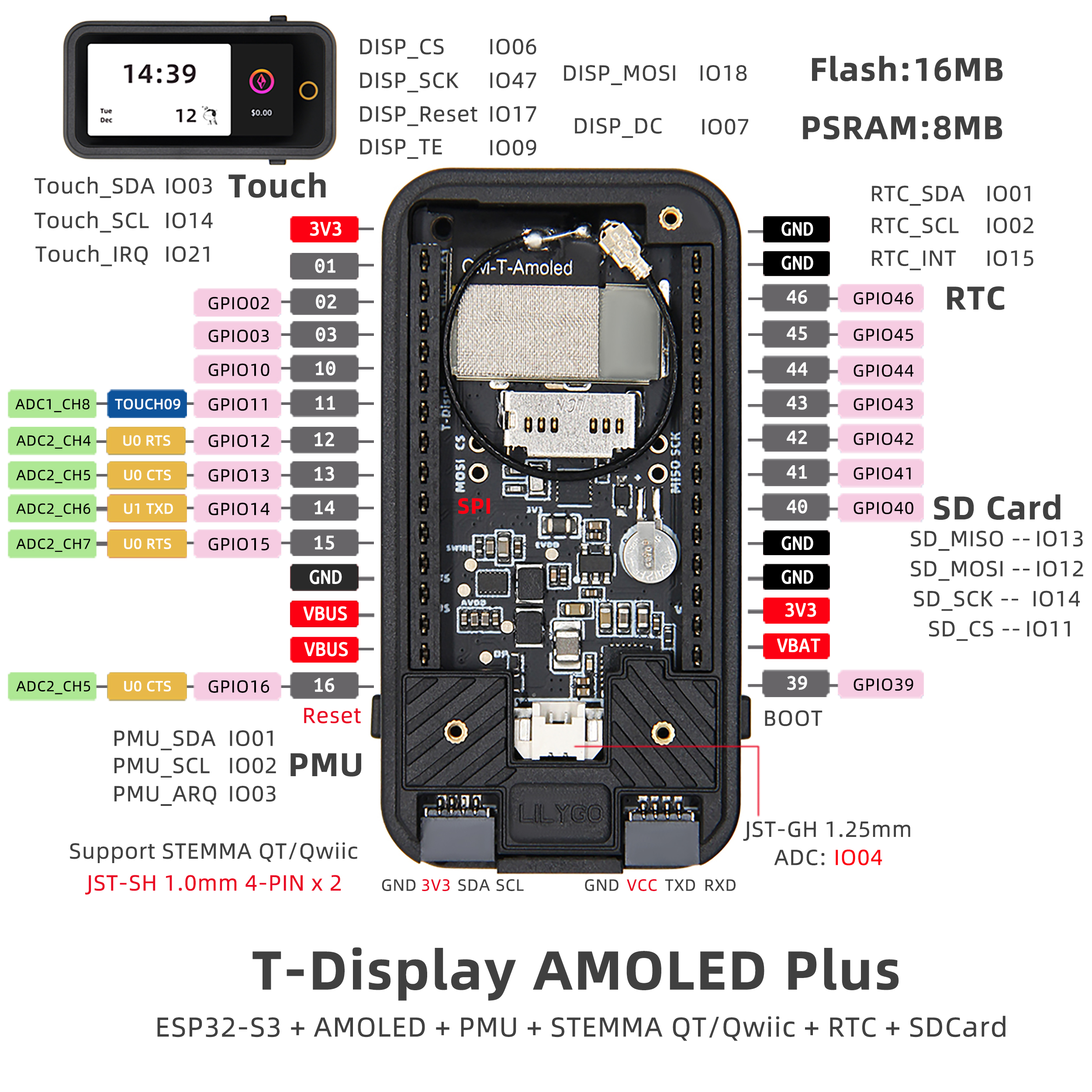
- Pin Overview
- Related Tests
- FAQ
- Projects
- Resources
- Dependent Libraries
Description
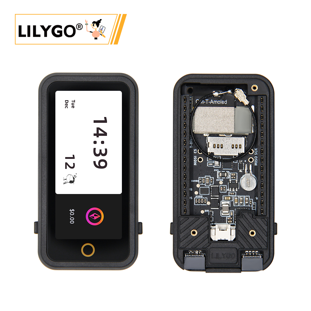
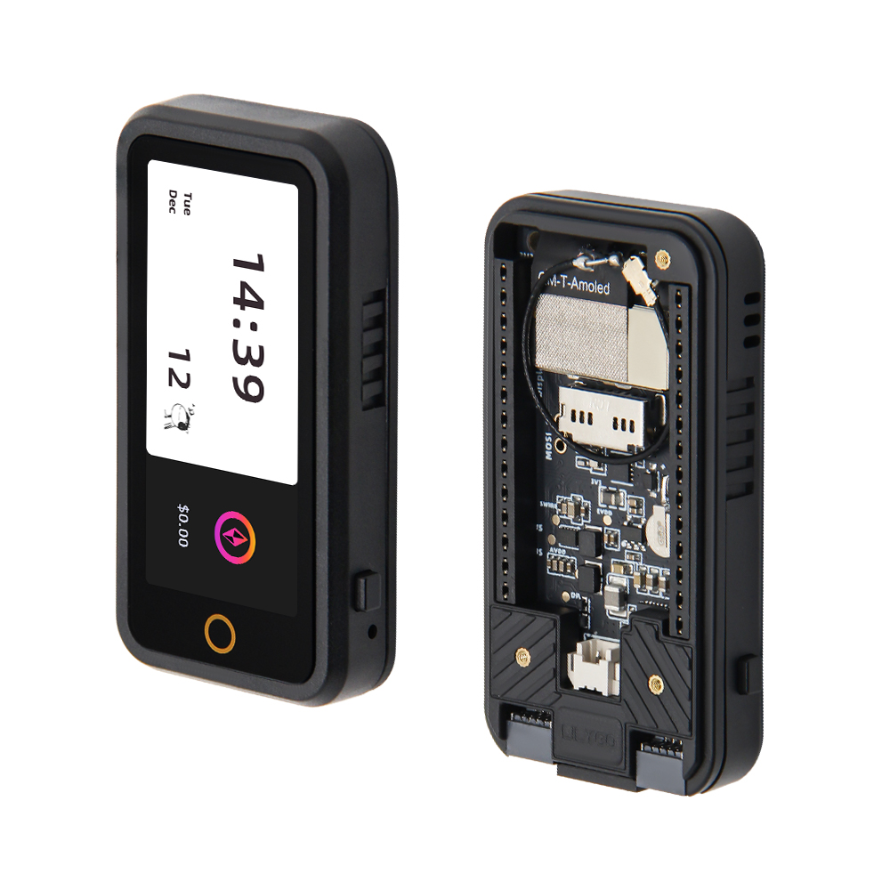
T-Display S3 AMOLED Plus is a highly integrated development board based on the ESP32-S3 microcontroller, focusing on multi-functionality and high performance. Its core features 16MB Flash and 8MB PSRAM, supporting complex application operations. Equipped with a 1.91-inch AMOLED display with touch support. Built-in PMU (Power Management Unit) and RTC (Real-Time Clock), combined with VBUS power management, optimize low-power design. For expansion, it provides dual STEMMA QT/Qwlic interfaces, compatible with quick sensor connections; supports SD card storage, and reserves rich GPIO, ADC channels, and UART communication interfaces for peripheral expansion. Additionally, onboard LoRa module supports multi-band communication. This product is suitable for smart wearables, IoT terminals, and other scenarios requiring display interaction and multi-sensor integration.
Preview
Physical Images
Pinout Diagram
Modules
MCU
- Chip: ESP32-S3-R8
- PSRAM: 8M (Octal SPI)
- FLASH: 16M
- Other Notes: For more information, please visit Espressif Official ESP32-S3 Datasheet
Screen
- Size: 1.91-inch AMOLED
- Resolution: To be added
- Type: IPS AMOLED
- Driver IC: RM67162
- Compatible Libraries: TFT_eSPI, Arduino_GFX
- Bus Protocol: SPI/QSPI
Touch
- Type: Capacitive Touch Screen
- Bus Protocol: I2C
LoRa
- Supported Bands: 1276/868/915MHz
Power Management
- PMU Chip: AXPM65611
- Charging Management: BQ25896
RTC
- Chip: PCF85063ATL/1
Overview
| Component | Description |
|---|---|
| MCU | ESP32-S3R8 Dual-core LX7 microprocessor |
| FLASH | 16MB |
| PSRAM | 8MB |
| Screen | 1.91-inch RM67162 IPS AMOLED |
| Touch | Capacitive Touch Screen |
| LoRa | 1276/868/915MHz |
| Storage | TF Card |
| RTC | PCF85063ATL/1 |
| Power Management | AXPM65611 + BQ25896 |
| Wireless | 2.4 GHz Wi-Fi & Bluetooth 5 (LE) |
| USB | 1 × USB Port and OTG (TYPE-C Interface) |
| IO Interface | 2×13 dual-row expansion interface |
| Expansion Interfaces | FPC antenna + TF Card + STEMMA QT/QWIIC + JST-GH 1.25MM |
| Buttons | 1 x RESET button + 1 x BOOT button |
| Mounting Holes | 4 × 2mm positioning holes |
| Dimensions | 60×32×12mm |
Quick Start
Example Support
| Example | PlatformIO/Arduino | ESP-IDF | Description |
|---|---|---|---|
| Factory | ✓ | Factory Example | |
| (More examples available in GitHub repository) |
PlatformIO
- Install Visual Studio Code according to your system.
- Open the "Extensions" sidebar in Visual Studio Code (or press Ctrl+Shift+X), search for the "PlatformIO IDE" extension and install it.
- While the extension is installing, download the project from GitHub. You can click the green "<> Code" button to download the main branch, or download a "Releases" version from the sidebar.
- After the extension installation is complete, open the Explorer sidebar (or press Ctrl+Shift+E), click "Open Folder", find the project code you just downloaded (the entire folder), click "Add", and the project files will be added to your workspace.
- Open the "platformio.ini" file in the project folder (PlatformIO should automatically open it after adding the folder). Under the "[platformio]" section, uncomment the line selecting the example program you want to upload (starting with "default_envs = xxx"). Then click the "√" at the bottom left to compile. If the compilation is successful, connect the board to your computer and click the "→" at the bottom left to upload.
Arduino
- Install Arduino IDE according to your system.
- Open the "example" directory in the project folder, select the example project folder, and open the file ending with ".ino" to open the Arduino IDE project workspace.
- Open the "Tools" menu -> "Board" -> "Boards Manager", find or search for "esp32", and install the board files by "Espressif Systems". Then return to the "Board" menu and select the board type under "ESP32 Arduino". The board type to choose is determined by the "board = xxx" header in the "[env]" section of the "platformio.ini" file. If the corresponding board is not available, you need to manually add the board from the "board" directory in the project folder.
- Open the "[File]" -> "[Preferences]" menu, find the "[Sketchbook location]" field. Copy and paste all library files and folders from the "libraries" directory in the project folder into the "libraries" folder at this location.
- Select the correct settings in the "Tools" menu as shown in the table below.
ESP32-S3
| Setting | Value |
|---|---|
| Board | ESP32S3 Dev Module |
| Upload Speed | 921600 |
| USB Mode | Hardware CDC and JTAG |
| USB CDC On Boot | Enabled |
| USB Firmware MSC On Boot | Disabled |
| USB DFU On Boot | Disabled |
| CPU Frequency | 240MHz (WiFi) |
| Flash Mode | QIO 80MHz |
| Flash Size | 16MB (128Mb) |
| Core Debug Level | None |
| Partition Scheme | 16M Flash (3MB APP/9.9MB FATFS) |
| PSRAM | OPI PSRAM |
| Arduino Runs On | Core 1 |
| Events Run On | Core 1 |
- Select the correct port.
- Click the "√" in the top right corner to compile. If the compilation is successful, connect the board to your computer and click the "→" to upload.
Development Platforms
Related Tests
(Power consumption and other test data to be added)
FAQ
Q. I still don't know how to set up the programming environment after reading the above tutorial. What should I do?
A. If you still don't understand how to set up the environment after reading the above tutorial, you can refer to the LilyGo-Document documentation for setup instructions.Q. Why does my board keep failing to upload programs?
A. Please hold down the "BOOT" button, then press the "RST" button once, and then click upload to enter download mode.Q. Which frequency bands does the LoRa module support?
A. Supports multiple frequency bands including 1276MHz, 868MHz, and 915MHz. Please select the appropriate frequency band according to regulations in your region.Q. How to fully utilize the power management functions?
A. Through the XPowersLib library, you can conveniently control the AXPM65611 power management chip and BQ25896 charging management chip to achieve low-power operation and battery management.Q. How to connect external sensors?
A. You can quickly connect compatible sensor modules through the onboard STEMMA QT/QWIIC interfaces, or connect other peripherals through the 2×13 dual-row expansion interface.
Projects
Resources
- ESP32-S3 Datasheet
- (More resources available in GitHub repository)