


 English
LILYGO T-Embed CC1101
Switch to T-Embed-SI4732 version here
Version History
| Version | Update Date | Update Description |
|---|---|---|
| T-Embed-CC1101_V1.0 | 2024-07-29 | Hardware |
| T-Embed-CC1101_V1.1 | 2025-01-09 | Software |
Purchase Links
| Product | SOC | FLASH | PSRAM | Link |
|---|---|---|---|---|
| T-Embed CC1101 | ESP32-S3 | 16MB | 8MB | LILYGO Store |
Table of Contents
- Description
- Preview
- Modules
- Quick Start
- Pin Overview
- Related Tests
- FAQ
- Projects
- Resources
- Dependent Libraries
Description
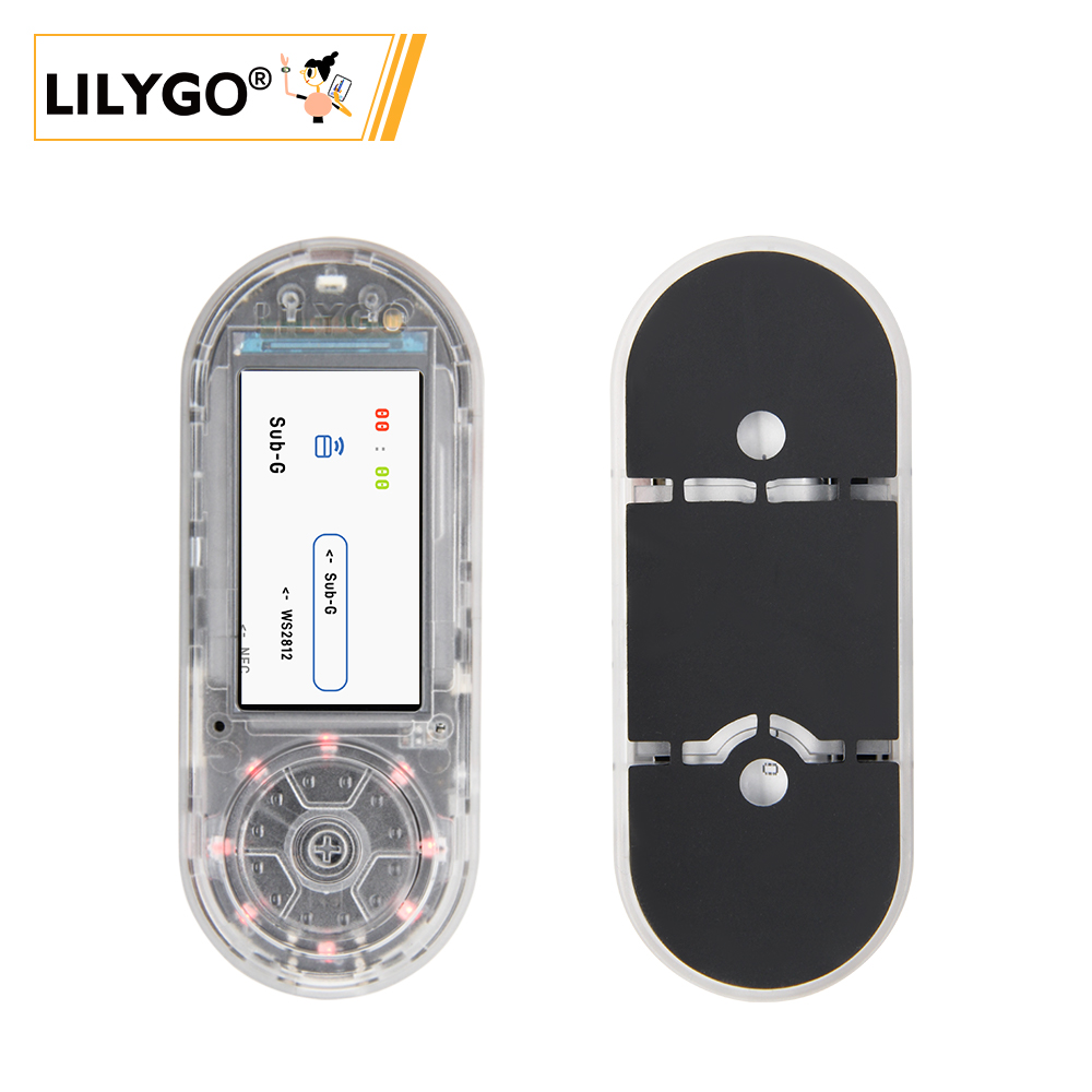
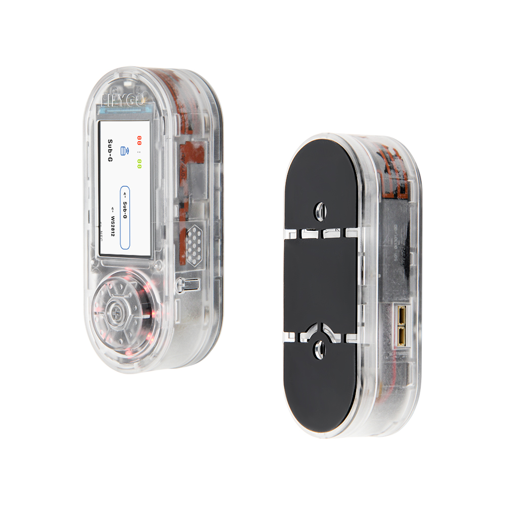
LILYGO T-Embed CC1101 is a highly integrated IoT development board based on the ESP32-S3 dual-core LX7 processor, specifically designed for multi-protocol communication and smart hardware development. It features onboard CC1101 Sub-GHz module, LoRa, PN532 NFC, infrared remote control, Wi-Fi 6 and Bluetooth 5.0, supporting complex scenarios such as remote sensing, smart home control, and industrial monitoring. Equipped with a 1.9-inch TFT screen, rotary encoder, 8 programmable RGB LEDs, microphone and speaker module, and supporting TF card expansion storage, it provides developers with an out-of-the-box, multi-scenario adaptable efficient hardware platform.
Preview
Physical Image
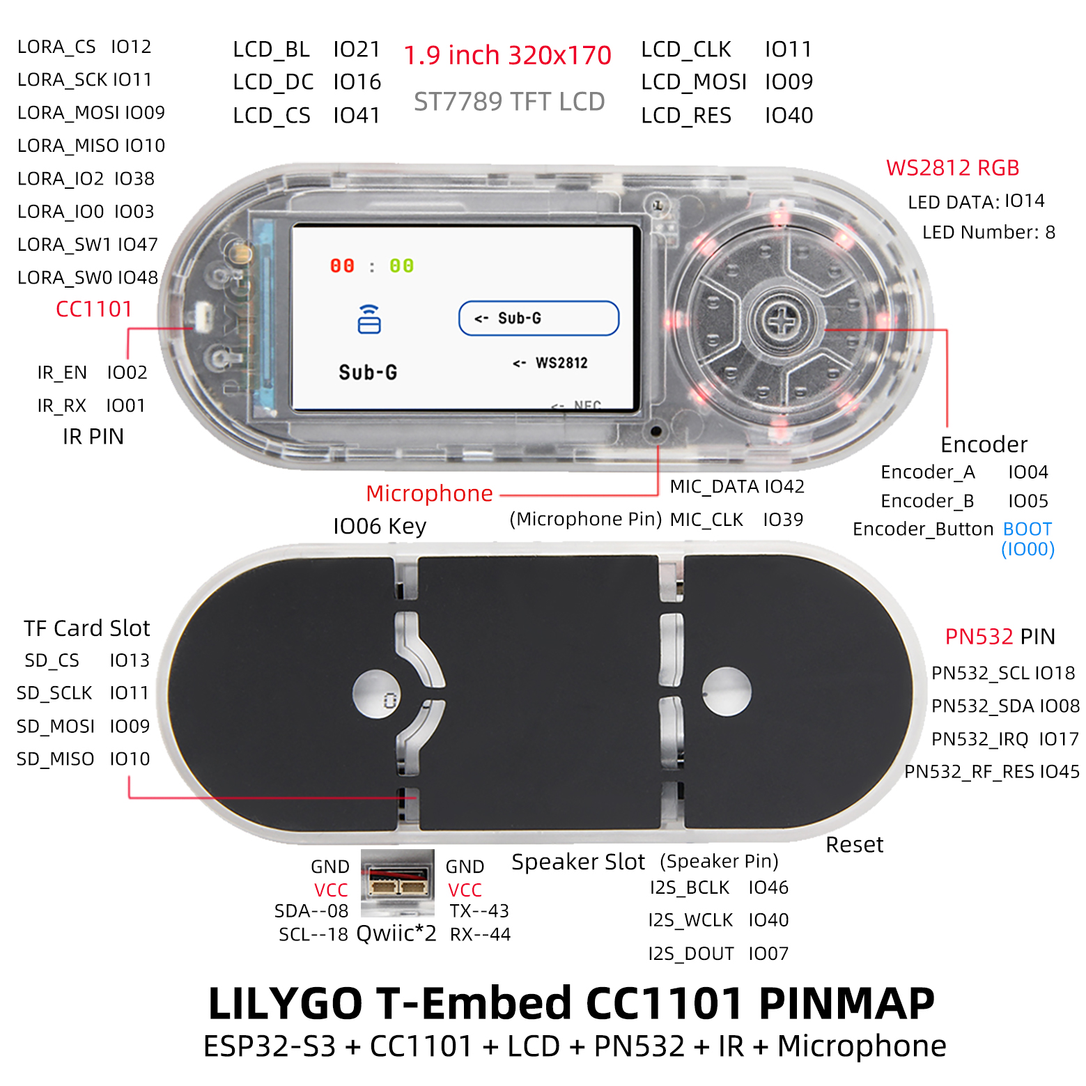
Pinout Diagram
Modules
MCU
- Chip: ESP32-S3FN16R8
- PSRAM: 8MB (Octal SPI)
- FLASH: 16MB
- Wireless: 2.4 GHz Wi-Fi & Bluetooth 5 (LE)
Display
- Size: 1.9-inch IPS TFT screen
- Resolution: 320×170px
- Display Type: IPS
- Driver IC: ST7789V
- Compatible Libraries: TFT_eSPI, LVGL
- Bus Communication Protocol: SPI
Communication Modules
- Sub-GHz: CC1101
- NFC: PN532
- GPS: MIA-M10Q (optional)
Audio System
- Audio Chip: ES7210
- Function: Microphone input and speaker output
Power Management
- Charging Chip: BQ25896
- Battery Monitoring: BQ27220
- Battery: 3.7V 1300mAh lithium polymer battery
Overview
| Component | Description |
|---|---|
| MCU | ESP32-S3FN16R8 Dual-core LX7 microprocessor |
| FLASH | 16MB |
| PSRAM | 8MB |
| Display | 1.9-inch ST7789V IPS TFT |
| Sub-GHz | CC1101 |
| NFC | PN532 |
| Audio | ES7210 Microphone and Speaker |
| Charging Chip | BQ25896 |
| Battery Monitoring | BQ27220 |
| RGB LED | 8 × WS2812 Programmable LEDs |
| Storage | TF Card |
| Wireless | 2.4 GHz Wi-Fi & Bluetooth 5 (LE) |
| USB | 1 × USB Port (TYPE-C Interface) |
| Control | Rotary Encoder |
| Buttons | 1 x RESET Button + 1 x BOOT Button |
| Dimensions | 97.5 × 39 × 31 mm |
Quick Start
Example Support
- ✅ bq25896_test : Battery management test, prints battery status in serial.
- ✅ cc1101_recv_irq : Wireless reception test, displays received messages in serial.
- ✅ cc1101_send_irq : Wireless transmission test, displays sent messages in serial.
- ✅ display_test : Screen display test;
- ✅ encode_test : Encoder test.
- ✅ infrared_recv_test: Infrared reception
- ✅ infrared_send_test: Infrared transmission
- ✅ lvgl_test : LVGL benchmark and stress test;
- ✅ pn532_test : NFC test, displays IC card information in serial.
- ✅ tf_card_test : SD card test, displays read file names in serial.
- ✅ record_test : Record 15 seconds of audio and save to SD card.
- ✅ voice_test : Speaker test, read audio from SD card.
- ✅ ws2812_test : LED light test;
PlatformIO
- Install VisualStudioCode, choose the version for your system.
- Open the "Extensions" in the sidebar of Visual Studio Code (or use Ctrl+Shift+X), search for the "PlatformIO IDE" extension and install it.
- While the extension is installing, you can go to GitHub to download the program. You can download the main branch code by clicking the green "<> Code" button, or download the "Releases" version from the sidebar.
- After the extension is installed, open the sidebar's Explorer (or use Ctrl+Shift+E), click "Open Folder", find the project code you just downloaded (the entire folder), click "Add", and the project files will be added to your workspace.
- Open the "platformio.ini" file in the project folder (PlatformIO will automatically open the "platformio.ini" of the corresponding folder after adding it). Under the "[platformio]" section, uncomment to select the example program you want to upload (marked by "default_envs = xxx"). Then click the "√" at the bottom left to compile. If the compilation is successful, connect the microcontroller to your computer and click "→" at the bottom left to upload.
Arduino
- Install Arduino IDE, choose the version for your system.
- Open the "example" directory in the project folder, select the example project folder, and open the file ending with ".ino" to open the Arduino IDE project workspace.
- Open the "Tools" menu in the top bar -> Select "Board" -> "Boards Manager", find or search for "esp32", and install the board files by "Espressif Systems". Then return to the "Board" menu and select the board type under "ESP32 Arduino". The board type to select is determined by the "board = xxx" header under the [env] section in the "platformio.ini" file. If the corresponding board is not available, you need to manually add the board from the "board" directory in the project folder.
- Open the menu bar "File" -> "Preferences", find the "Sketchbook location" field, and copy all the library files along with their folders from the "libraries" folder in the project directory to the "libraries" folder in this location.
- Select the correct settings in the "Tools" menu as shown in the table below.
ESP32-S3
| Setting | Value |
|---|---|
| Board | ESP32S3 Dev Module |
| Upload Speed | 921600 |
| USB Mode | Hardware CDC and JTAG |
| USB CDC On Boot | Enabled |
| USB Firmware MSC On Boot | Disabled |
| USB DFU On Boot | Disabled |
| CPU Frequency | 240MHz (WiFi) |
| Flash Mode | QIO 80MHz |
| Flash Size | 16MB (128Mb) |
| Core Debug Level | None |
| Partition Scheme | 16M Flash (3MB APP/9.9MB FATFS) |
| PSRAM | OPI PSRAM |
| Arduino Runs On | Core 1 |
| Events Run On | Core 1 |
- Select the correct port.
- Click the "√" in the top right corner to compile. If the compilation is successful, connect the microcontroller to your computer and click "→" in the top right corner to upload.
Development Platforms
Pin Overview
#define BOARD_USER_KEY 6
#define BOARD_PWR_EN   15

// WS2812
#define WS2812_NUM_LEDS 8
#define WS2812_DATA_PIN 14

// IR
#define BOARD_IR_EN 2
#define BOARD_IR_RX 1

// MIC
#define BOARD_MIC_DATA 42
#define BOARD_MIC_CLK  39

// VOICE
#define BOARD_VOICE_BCLK  46
#define BOARD_VOICE_LRCLK 40
#define BOARD_VOICE_DIN   7

// --------- DISPLAY ---------
// About LCD definition in the file: lib/TFT_eSPI/User_Setups/Setup214_LilyGo_T_Embed_PN532.h
#define DISPLAY_WIDTH  170
#define DISPLAY_HEIGHT 320

#define DISPLAY_BL   21
#define DISPLAY_CS   41
#define DISPLAY_MISO -1
#define DISPLAY_MOSI  9
#define DISPLAY_SCLK 11
#define DISPLAY_DC   16
#define DISPLAY_RST  40

// --------- ENCODER ---------
#define ENCODER_INA 4
#define ENCODER_INB 5
#define ENCODER_KEY 0

// --------- IIC ---------
#define BOARD_I2C_SDA  8
#define BOARD_I2C_SCL  18

// IIC addr
#define BOARD_I2C_ADDR_1 0x24  // PN532
#define BOARD_I2C_ADDR_2 0x55  // BQ27220
#define BOARD_I2C_ADDR_3 0x6b  // BQ25896

// NFC
#define BOARD_PN532_SCL     BOARD_I2C_SCL
#define BOARD_PN532_SDA     BOARD_I2C_SDA
#define BOARD_PN532_RF_REST 45
#define BOARD_PN532_IRQ     17

// --------- SPI ---------
#define BOARD_SPI_SCK  11
#define BOARD_SPI_MOSI 9
#define BOARD_SPI_MISO 10

// TF card
#define BOARD_SD_CS   13
#define BOARD_SD_SCK  BOARD_SPI_SCK
#define BOARD_SD_MOSI BOARD_SPI_MOSI
#define BOARD_SD_MISO BOARD_SPI_MISO

// LORA
#define BOARD_LORA_CS   12
#define BOARD_LORA_SCK  BOARD_SPI_SCK
#define BOARD_LORA_MOSI BOARD_SPI_MOSI
#define BOARD_LORA_MISO BOARD_SPI_MISO
#define BOARD_LORA_IO2  38
#define BOARD_LORA_IO0  3
#define BOARD_LORA_SW1  47
#define BOARD_LORA_SW0  48
Related Tests
FAQ
What if I still can't set up the programming environment after reading the above tutorial?
If you still don't understand how to set up the environment after reading the above tutorial, you can refer to the LilyGo-Document documentation for setup instructions.
How to troubleshoot when equipment malfunctions?
If equipment malfunctions occur (cannot power on/black screen), please troubleshoot according to the following steps:
- First check if the device's
power supplyis normal and if the battery is sufficient; - Then check if the device is connected to the computer and can be
recognized; - Then check if the device has been properly flashed with the
firmware; - Finally, check if the device powers on normally and if the screen displays normally.
- For the steps to download the factory firmware, you can refer to the Download Instructions.
If the above steps cannot solve the problem, please record a video of the factory firmware download process and also provide us with the corresponding serial port print information.
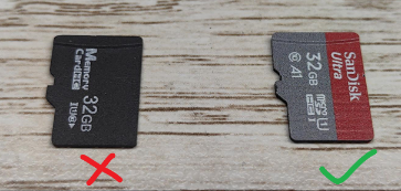
Cannot detect SD card?
We successfully tested SD cards up to 32GB using SanDisk; but some other cards did not work, the reason is unclear. Therefore, if an SD card is not detected, it is recommended to replace it with a SanDisk card not larger than 32GB.
Why does my board keep failing to upload programs?
Please hold down the "BOOT" button and press the "RST" button simultaneously, then release the "RST" button to enter download mode, and try uploading the program again.
What is the communication distance of the CC1101 module?
The communication distance of CC1101 is affected by various factors, including antenna design, environmental interference, data rate, etc., and can reach hundreds of meters under ideal conditions.
NFC not working
After flashing the factory firmware, open the NFC interface and use the NFC tag we provided as a detection object. If it cannot be recognized, please check the following:
- Is the tag properly attached;
- Is the tag correctly connected to the device;
- Has the device been properly flashed with the correct firmware;
- Has the device correctly enabled NFC function;
| Problem | Link |
|---|---|
| How do I enter download mode? | docs |
| How to download the program? | docs |
| How do I turn on the device after I shut it down? | Issues #5 |
| How do I configure Wifi with EspTouch? | Issues #4 |
| Why won't the battery charge? | Issues #9 |