


 English
LILYGO T-Connect
Version History:
| Version | Update date | Update description |
|---|---|---|
| T-Connect_V1.0 | Initial Version |
Purchase Links
| Product | SOC | FLASH | PSRAM | Link |
|---|---|---|---|---|
| T-Connect | ESP32-S3-R8 | 16MB | 8MB (Octal SPI) | LILYGO Mall |
Table of Contents
- Description
- Preview
- Modules
- Quick Start
- Pin Overview
- Related Tests
- FAQ
- Projects
- Resources
- Dependent Libraries
Description
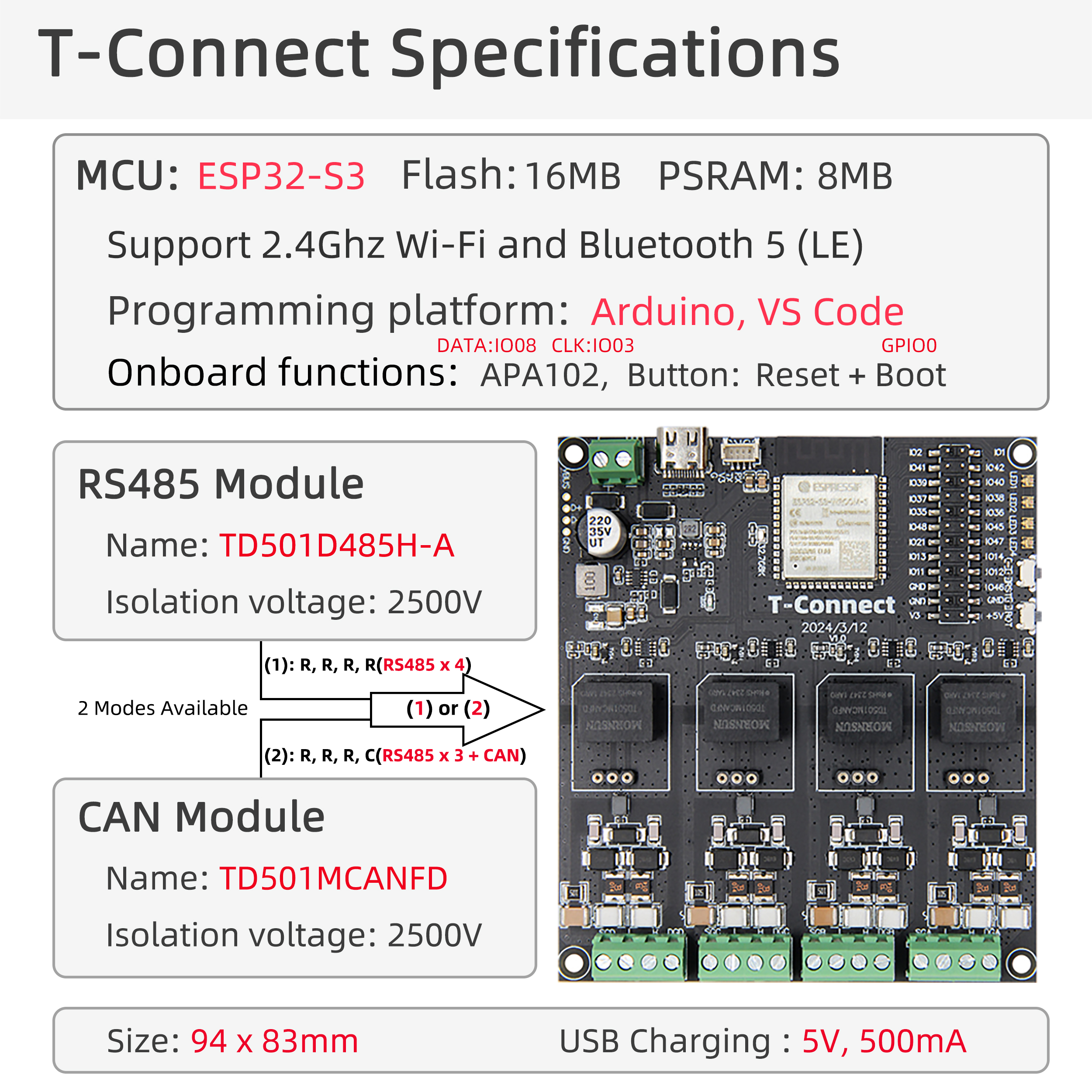
T-Connect is a multi-functional development board based on the ESP32-S3 chip, equipped with 8MB PSRAM and 16MB Flash, supporting Wi-Fi/Bluetooth dual-mode communication and RS485/CAN industrial protocols, with built-in APA102 LED driver for direct control of RGB light strips. Its rich UART interfaces and multiplexed pins (such as SGD/SGC series) are suitable for IoT devices, industrial automation, smart lighting, and other scenarios, combining high integration with expansion flexibility, suitable for stable communication and diverse control requirements in complex environments.
Core Features
- Multi-protocol Support: Supports up to three sets of RS485 and one set of CAN bus outputting different data
- Industrial Communication: Supports RS485 and CAN bus industrial protocols
- Flexible Configuration: Supports switching between CAN and RS485 modules
- Rich Interfaces: Integrated relay, LED control, QWIIC expansion interface
- Industrial Design: Wide voltage input, 4 positioning holes for easy installation and fixation
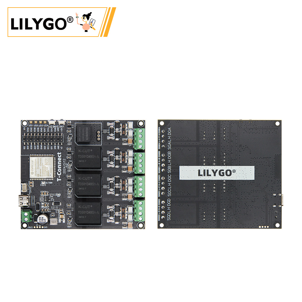
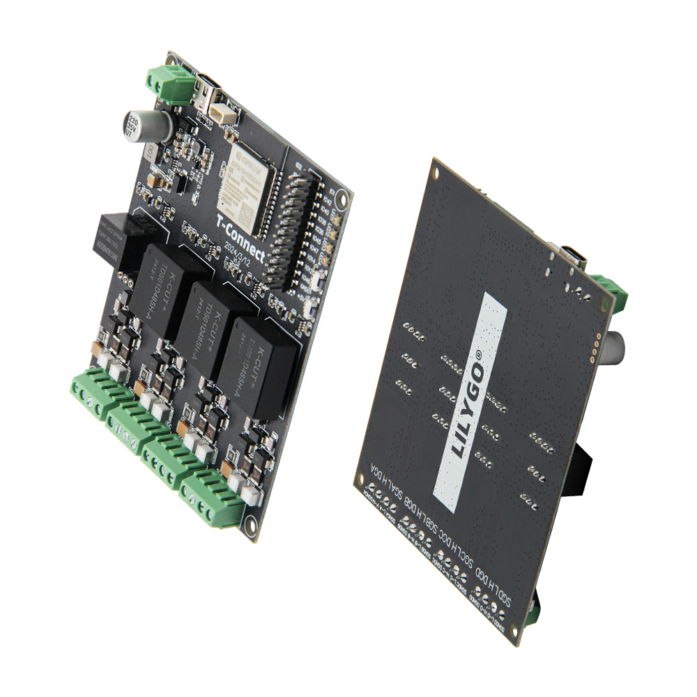
Preview
Physical Image
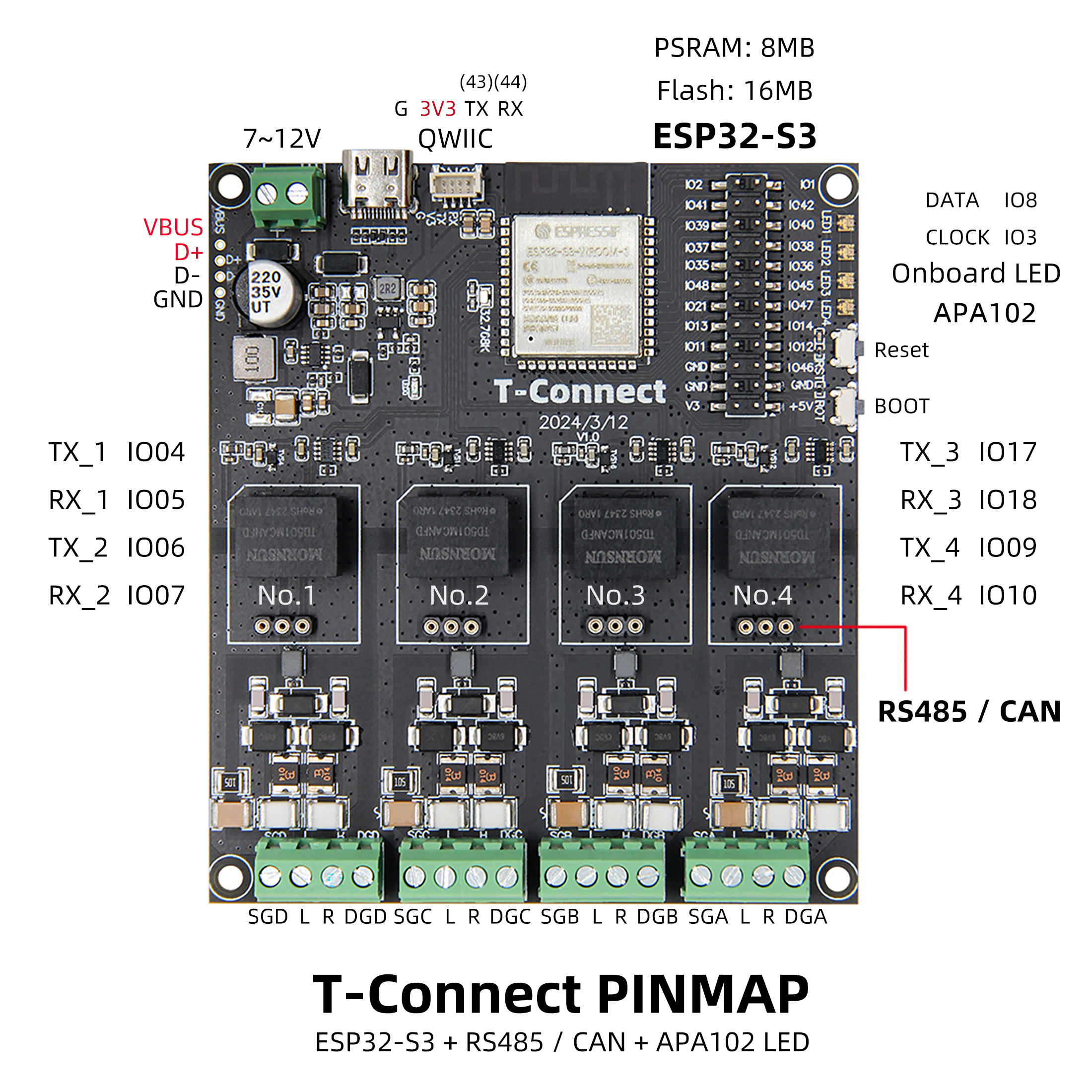
Pin Diagram
Modules
MCU
- Chip: ESP32-S3-R8
- PSRAM: 8M (Octal SPI)
- FLASH: 16M
- Wireless: Wi-Fi 802.11 b/g/n; Bluetooth 5.0 (BLE)
- Additional Information: More information available at Espressif Official ESP32-S3 Datasheet
Communication Interfaces
- RS485: Supports up to 3 sets of RS485 communication (UART protocol)
- CAN: Supports 1 set of CAN bus communication (TWAI protocol)
- Module Switching: Supports switching configuration between CAN and RS485 modules
Peripheral Control
- LED Driver: APA102 RGB light strip control
- Relay: 10A output capability
- Expansion Interface: QWIIC ecosystem interface
Power Management
- Input Voltage: 7V-12V DC
- USB Power Supply: 5V/500mA Type-C interface
Overview
T-Connect is a board with 4 sets of different module output data, supporting switching between CAN and RS485 modules, with maximum support for three sets of RS485 and one set of CAN bus outputting different data.
| Component | Description |
|---|---|
| MCU | ESP32-S3-R8 |
| FLASH | 16MB |
| PSRAM | 8MB (Octal SPI) |
| Communication Protocols | RS485 (UART) / CAN (TWAI) |
| LED Driver | APA102 |
| Relay | 10A Output |
| Wireless | 2.4 GHz Wi-Fi & Bluetooth 5 (LE) |
| USB | 1 × USB Port and OTG (TYPE-C) |
| Output Configuration | Maximum support for three sets of RS485 + one set of CAN bus |
| Expansion Interface | 1 × QWIIC Interface |
| Buttons | 1 x RESET Button + 1 x BOOT Button |
| Power Input | 7V~12V DC + 5V/500mA USB |
| Mounting Holes | 4 × 2mm Positioning Holes |
| Dimensions | 94×83×13mm |
Quick Start
Example Support
| Example | Support IDE And Version | Description | Picture |
|---|---|---|---|
| Original_Test | [Platformio IDE][espressif32-v6.5.0][Arduino IDE][esp32_v2.0.14] |
Factory Initial Test File | |
| APA102_Blink | [Platformio IDE][espressif32-v6.5.0][Arduino IDE][esp32_v2.0.14] |
||
| CAN | [Platformio IDE][espressif32-v6.5.0][Arduino IDE][esp32_v2.0.14] |
||
| RS485 | [Platformio IDE][espressif32-v6.5.0][Arduino IDE][esp32_v2.0.14] |
| Firmware | Description | Picture |
|---|---|---|
| Original_Test | Factory Initial Test File |
PlatformIO
- Install Visual Studio Code, choose the installation according to your system type.
- Open the "Extensions" in the sidebar of Visual Studio Code (or use Ctrl+Shift+X to open extensions), search for the "PlatformIO IDE" extension and install it.
- While the extension is installing, you can go to GitHub to download the program. You can download the main branch program by clicking the green "<> Code" button, or download the "Releases" version from the sidebar.
- After the extension is installed, open the sidebar's Explorer (or use Ctrl+Shift+E to open it), click "Open Folder", find the project code you just downloaded (the entire folder), click "Add", and the project files will be added to your workspace.
- Open the "platformio.ini" file in the project folder (PlatformIO will automatically open the "platformio.ini" of the corresponding folder after successfully adding the folder). Under the "[platformio]" section, uncomment and select the example program you want to upload (marked with "default_envs = xxx"). Then click the "√" at the bottom left to compile. If the compilation is successful, connect the microcontroller to the computer and click the "→" at the bottom left to upload.
Arduino
- Install Arduino IDE, choose the installation according to your system type.
- Open the "example" directory in the project folder, select the example project folder, and open the file ending with ".ino" to open the Arduino IDE project workspace.
- Open the "Tools" menu in the upper right corner -> Select "Board" -> "Board Manager", find or search for "esp32", and download the board files by the author "Espressif Systems". Then return to the "Board" menu and select the development board type under "ESP32 Arduino". The selected development board type should be based on the "board = xxx" header under the [env] directory in the "platformio.ini" file. If there is no corresponding development board, you need to manually add the development board from the "board" directory in the project folder.
- Open the "File" -> "Preferences" menu, find the "Sketchbook location" field, and copy all the library files along with their folders from the "libraries" folder in the project directory to the "libraries" folder in this directory.
- Select the correct settings in the "Tools" menu as shown in the table below.
ESP32-S3
| Setting | Value |
|---|---|
| Board | ESP32S3 Dev Module |
| Upload Speed | 921600 |
| USB Mode | Hardware CDC and JTAG |
| USB CDC On Boot | Enabled |
| USB Firmware MSC On Boot | Disabled |
| USB DFU On Boot | Disabled |
| CPU Frequency | 240MHz (WiFi) |
| Flash Mode | QIO 80MHz |
| Flash Size | 16MB (128Mb) |
| Core Debug Level | None |
| Partition Scheme | 16M Flash (3MB APP/9.9MB FATFS) |
| PSRAM | OPI PSRAM |
| Arduino Runs On | Core 1 |
| Events Run On | Core 1 |
- Select the correct port.
- Click the "√" in the upper right corner to compile. If the compilation is successful, connect the microcontroller to the computer and click the "→" in the upper right corner to upload.
Development Platforms
Pin Overview
| LED Pins | ESP32S3 Pins |
|---|---|
| APA102_DATA | IO8 |
| APA102_CLOCK | IO3 |
| CAN and RS485 Shared Pins | ESP32S3 Pins |
|---|---|
| TX_1 | IO4 |
| RX_1 | IO5 |
| TX_2 | IO6 |
| RX_2 | IO7 |
| TX_3 | IO17 |
| RX_3 | IO18 |
| TX_4 | IO9 |
| RX_4 | IO10 |
Related Tests
| Board | Program | Description | Picture |
|---|---|---|---|
T-Connect_V1.0 |
CAN |
Speed: 500KBITS Communication Distance: 35m |
|
T-Connect_V1.0 |
RS485 |
Baud Rate: 115200 Communication Distance: 35m |
FAQ
Q. I still don't know how to set up the programming environment after reading the above tutorial. What should I do?
A. If you still don't understand how to set up the environment after reading the above tutorial, you can refer to the LilyGo-Document documentation for setup instructions.Q. Why does Arduino IDE prompt me to update library files when I open it? Should I update or not?
A. Choose not to update library files. Different versions of library files may not be compatible with each other, so it is not recommended to update library files.Q. How to configure switching between RS485 and CAN modules?
A. Switching between RS485 and CAN modules is achieved through onboard configuration jumpers or software settings. For specific configuration methods, please refer to the schematic diagram and example code.Q. Why does my board keep failing to upload programs?
A. Please hold down the "BOOT" button and try uploading the program again.