


 English
LILYGO T-Display-S3-Long

Version History:
| Version | Update date | Update description |
|---|---|---|
| T-Display-S3-Long_V1.0 | Latest Version | Initial version of long strip display development board |
Purchase Links
| Product | SOC | FLASH | PSRAM | Resolution | Screen Type | Link |
|---|---|---|---|---|---|---|
| T-Display-S3-Long | ESP32-S3R8 | 16M | 8M (OPI) | 180×640 | AMOLED | LILYGO Mall |
Table of Contents
- Description
- Preview
- Modules
- Quick Start
- Pin Overview
- Related Tests
- FAQ
- Projects
- Resources
- Dependent Libraries
Description
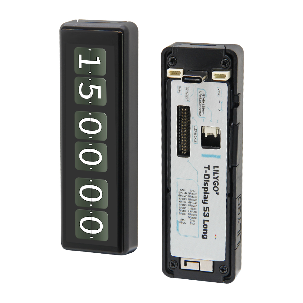
T-Display-S3-Long is a long strip display development board based on ESP32-S3, using a 180×640 resolution AMOLED screen, providing a unique vertical display experience. The development board is equipped with ESP32-S3R8 dual-core processor, 16MB Flash storage, and 8MB OPI PSRAM memory, delivering strong performance.
It features a capacitive touch screen, QWIIC sensor interface, power management chip, and Type-C USB interface, supporting Wi-Fi and Bluetooth 5.0 wireless communication. The compact long strip design is suitable for smart home control panels, industrial instrument displays, information display terminals, and other application scenarios.
Preview
Physical Image
Modules
MCU
- Chip: ESP32-S3R8
- PSRAM: 8MB (Octal SPI)
- FLASH: 16MB
- Architecture: Dual-core Xtensa LX7
- Wireless: Wi-Fi 802.11b/g/n + Bluetooth 5.0
Display
- Size: Long strip AMOLED
- Resolution: 180x640px
- Display Type: AMOLED
- Driver Chip: AXS15231B
- Interface: SPI/QSPI
Touch
- Type: Capacitive touch screen
- Interface: I2C
Power Management
- Chip: Built-in PMU
- Function: Supports battery charge and discharge management
- OTG: Supports power supply for external devices
Overview

| Component | Description |
|---|---|
| MCU | ESP32-S3R8 Dual-core Processor |
| FLASH | 16MB |
| PSRAM | 8MB (OPI) |
| Display | 180×640 AMOLED |
| Touch | Capacitive Touch Screen |
| Wireless | Wi-Fi 802.11b/g/n + Bluetooth 5.0 |
| USB | 1 × USB Port (TYPE-C) |
| Interface | QWIIC Sensor Interface |
| Buttons | BOOT + RST |
| Power Consumption | Working: 90-350mA, Sleep: 1.1mA |
| GPIO Wakeup | Supported |
Quick Start
Example Programs
| Example Directory | Description |
|---|---|
| Factory | Factory Test Program |
| tft | Screen Display Test |
| touch | Touch Function Test |
| QWIIC_Sensor | QWIIC Sensor Example |
| GFX_AXS15231B_Image | Graphics Image Display |
| lvgl_demo | LVGL Graphical Interface Demo |
PlatformIO Development (Recommended)
- Install Visual Studio Code and Python
- Search for and install "PlatformIO IDE" in VS Code extensions
- Restart VS Code to complete installation
- Open project folder:
File→Open Folder→ selectT-Display-S3-Longdirectory - Wait for third-party libraries to be automatically installed
- Edit the
platformio.inifile, uncomment the required example path in the[platformio]section - Click
✔at the bottom left to compile the project - Connect the development board to the computer USB port
- Click
→to upload firmware - Click
🔌icon to view serial output
Arduino IDE Development
- Install Arduino IDE
- Download or clone the T-Display-S3-Long project
- Copy all files in
T-Display-S3-Long/libto the Arduino library folder - Open the project example via
File→Open - Configure development board parameters:
- Select the correct port
- Click the upload button, wait for compilation and flashing to complete
ESP32 Basic Examples
- BLE Examples
- WiFi Examples
- SPIFFS Examples
- FFat Examples
- For more ESP32 function examples, refer to arduino-esp32-libraries
Development Platforms
- Platform IO - Recommended
- Arduino IDE
- ESP-IDF
Pin Overview
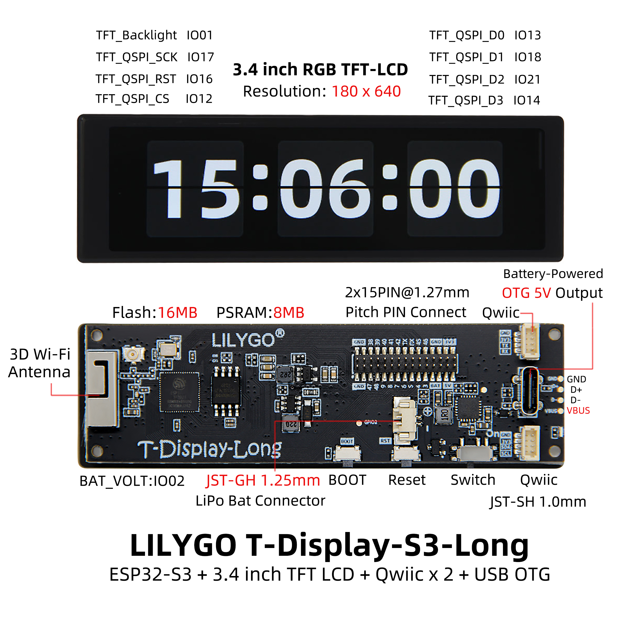
#define TFT_QSPI_CS           12
#define TFT_QSPI_SCK          17
#define TFT_QSPI_D0           13
#define TFT_QSPI_D1           18
#define TFT_QSPI_D2           21
#define TFT_QSPI_D3           14
#define TFT_QSPI_RST          16
#define TFT_BL                1


#define PIN_BAT_VOLT          2

#define PIN_BUTTON_1          0
#define PIN_BUTTON_2          21

#define SPI_SD_CS            38
#define SPI_SD_MOSI           39
#define SPI_SD_MISO           41
#define SPI_SD_SCLK           40


#define TOUCH_IICSCL 10
#define TOUCH_IICSDA 15
#define TOUCH_INT    11
#define TOUCH_RES    16
Related Tests
Power Consumption Test
| Working Mode | Current Consumption | Description |
|---|---|---|
| Normal Operation | 90-350mA | Wi-Fi on, 240MHz frequency |
| Sleep Mode | 1.1mA | Low power standby |
| GPIO Wakeup | To be tested | External interrupt wakeup |
FAQ
Q. What to do if the development board cannot flash programs?
A. Manually enter download mode:- Connect the development board via USB
- Hold down the BOOT button
- Press the RST button while holding BOOT
- Release RST first, then release BOOT
- Now you can upload the program normally
Q. USB device frequently disconnects?
A. Check USB cable quality, try other USB ports, ensure stable power supply.Q. How to use OTG function?
A. Need to enable PMU OTG function via software:PMU.enableOTG(); // Enable OTG power output PMU.disableOTG(); // Disable OTG power outputQ. Battery charging indicator flashing?
A. When no battery is connected and only USB is connected, the status indicator will flash. You can usePMU.disableStatLed()to turn off the indicator, but this will also disable the charging status indication. To enable, callPMU.enableStatLed().Q. Purpose of the physical switch?
A. Switching the physical switch to OFF will completely disconnect the battery from the main board. When charging is required, switch to ON.Q. Firmware verification method?
A. If you encounter problems, you can flash the pre-compiled firmware to verify if the hardware is normal.
Projects
Resources
Dependent Libraries
- LVGL 8.3.0 - Embedded graphics library (Note: do not upgrade version, software rotation has been forced open)
- XPowersLib - Power management library
- Arduino_GFX - Graphics display library
- Adafruit_BusIO - Bus communication library
- TFT_eSPI - TFT display driver library