


 English
LILYGO T-Beam 1W
Version History:
| Version | Update date | Update description |
|---|---|---|
| T-Beam-1W_V1.0 | 2024-06-15 | Initial Version |
| T-Beam-1W_V1.1 | 2024-08-22 | Optimized power circuit, added fan control |
Purchase Links
| Product | SOC | FLASH | PSRAM | PMU | Link |
|---|---|---|---|---|---|
| T-Beam-1W | ESP32-S3FN8 | 16MB | 8MB (OPI PSRAM) | AXP2101 | LILYGO Mall |
Table of Contents
- Overview
- Functional Block Diagram
- Specifications
- Quick Start
- Pin Mapping
- Electrical Parameters
- Buttons and LED Description
- RF Parameters and Precautions
- FAQ
- Resource Downloads
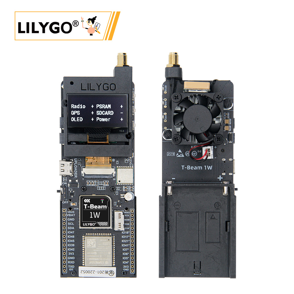
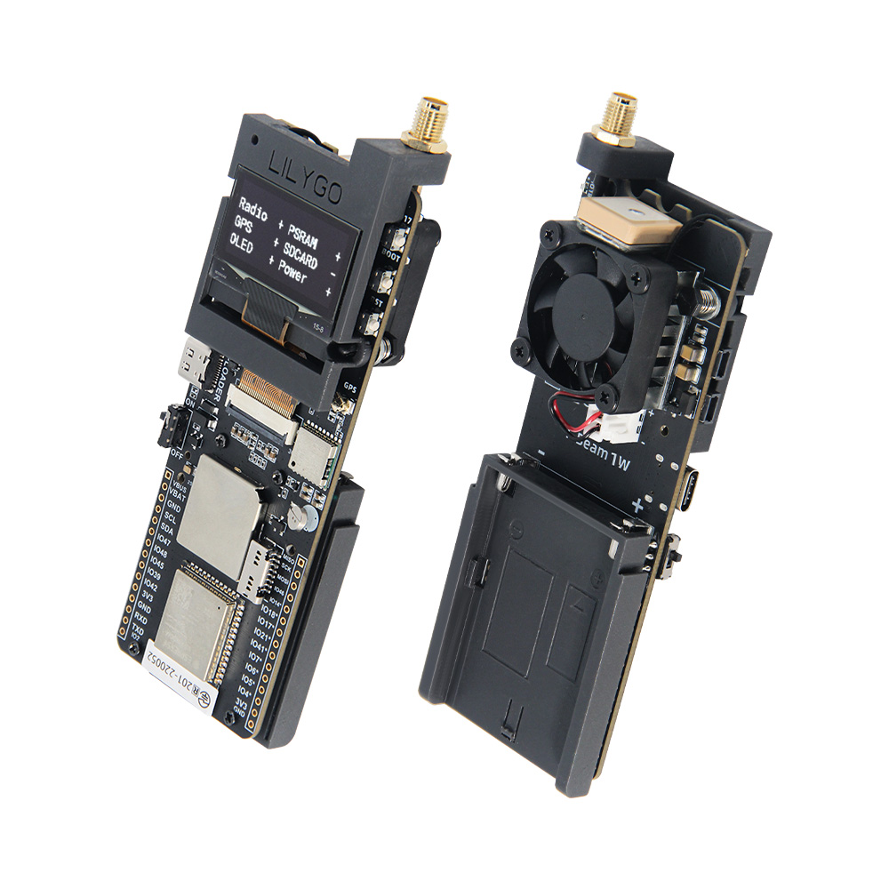
Overview
T-Beam-1W is a high-performance IoT development board integrating ESP32-S3 dual-core processor, LoRa SX1262 module, GPS L76K positioning module, SH1106 OLED screen, and AXP2101 power management chip. Onboard TF card slot, QWIIC interface, external antenna interface, supporting Wi-Fi, Bluetooth 5.0 and LoRa communication, suitable for long-distance communication, positioning tracking, environmental monitoring, and other application scenarios.
Usage Notes:
- This board does not charge external 7.4V batteries, only powered by batteries.
- Always connect the antenna before transmission to avoid damaging the RF module.
- GPIOs marked with * in the pin table are already connected to internal modules and cannot be reused.
- The maximum output power of the RF module on this board is 32dBm.
Physical Image
Specifications
| Component | Specification |
|---|---|
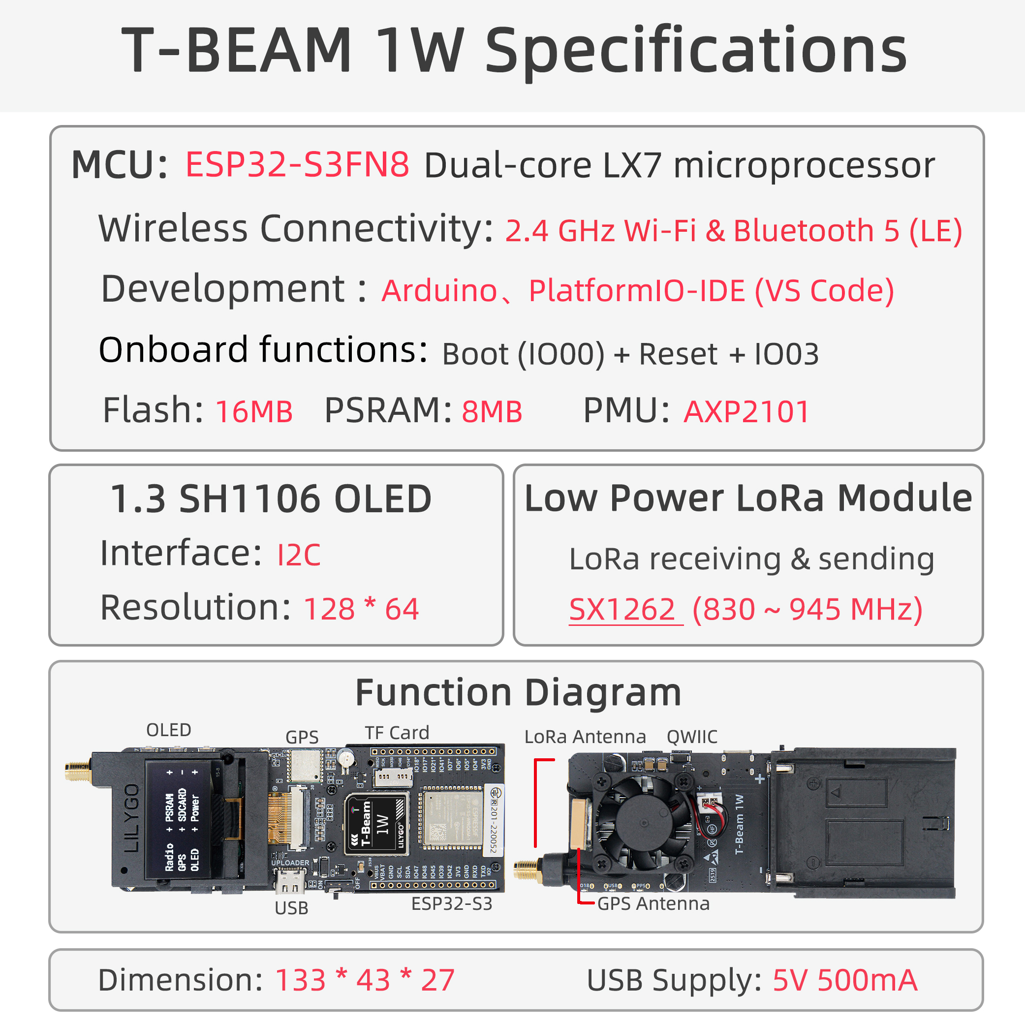
| MCU | ESP32-S3FN8, dual-core LX7, 240MHz |
| Wireless | Wi-Fi 2.4GHz + Bluetooth 5.0 LE |
| LoRa Module | SX1262, supports 830~945MHz |
| GPS Module | L76K, supports multi-constellation positioning |
| Display | 1.3-inch SH1106 OLED, 128×64 resolution |
| Storage | 16MB Flash + 8MB PSRAM, supports TF card expansion |
| Power Management | AXP2101, supports USB-C power supply, 7.4V battery input |
| Interfaces | QWIIC, UART, SPI, I2C, TF card slot |
| Buttons | BOOT, RESET, custom button |
| Dimensions | 133 × 43 × 27 mm |
| USB Power Supply | 5V / 500mA |
Quick Start
PlatformIO Environment Setup
- Install Visual Studio Code and Python
- Search for and install the
PlatformIOplugin inVisual Studio Codeextensions - After installation is complete, you need to restart
Visual Studio Code - After restarting, select
File->Open Folder-> select theLilyGo-LoRa-Seriesdirectory - Wait for third-party dependency libraries to install
- Click to open the
platformio.inifile, under theplatformiosection - Under
default_envs, select the development board name you want to use and uncomment it - Uncomment one line of
src_dir = xxxxto ensure only one line is active. Please note the example comments, which explain which features are available and which are not. - Click the (✔) symbol at the bottom left to compile
- Connect the development board to the computer using a USB-C cable (Micro-USB interface is for module firmware upgrade)
- Click (→) to upload firmware
- Click (plug symbol) to monitor serial output
- If unable to write or USB device keeps flashing, please check the FAQ below
Arduino IDE Environment Setup
- Install Arduino IDE
- Install Arduino ESP32
- Copy all folders in the
libdirectory to theSketchbook locationdirectory. To find your own library location, refer to: https://support.arduino.cc/hc/en-us/articles/4415103213714-Find-sketches-libraries-board-cores-and-other-files-on-your-computer
- Windows:
C:\Users\{username}\Documents\Arduino - macOS:
/Users/{username}/Documents/Arduino - Linux:
/home/{username}/Arduino
- Open the corresponding example
- Open the downloaded
LilyGo-LoRa-Series - Open
examples - Select the example file and open the file ending with
ino
- Select the corresponding development board in the Arduino IDE Tools menu, and click the corresponding option in the list below to select.
| Name | Value |
|---|---|
| Board | ESP32S3 Dev Module |
| Port | Your port |
| USB CDC On Boot | Enable |
| CPU Frequency | 240MHZ(WiFi) |
| Core Debug Level | None |
| USB DFU On Boot | Disable |
| Erase All Flash Before Sketch Upload | Disable |
| Flash Mode | QIO 80Mhz |
| Flash Size | 16MB(128Mb) |
| Arduino Runs On | Core1 |
| USB Firmware MSC On Boot | Disable |
| Partition Scheme | 16M Flash (3MB APP/9.9MB FATFS) |
| PSRAM | OPI PSRAM |
| Upload Speed | 921600 |
| Programmer | Esptool |
- Please uncomment the
utilities.hfile of each sketch according to your board model (e.g.,T_BEAM_1W), otherwise compilation will report an error - Upload the example
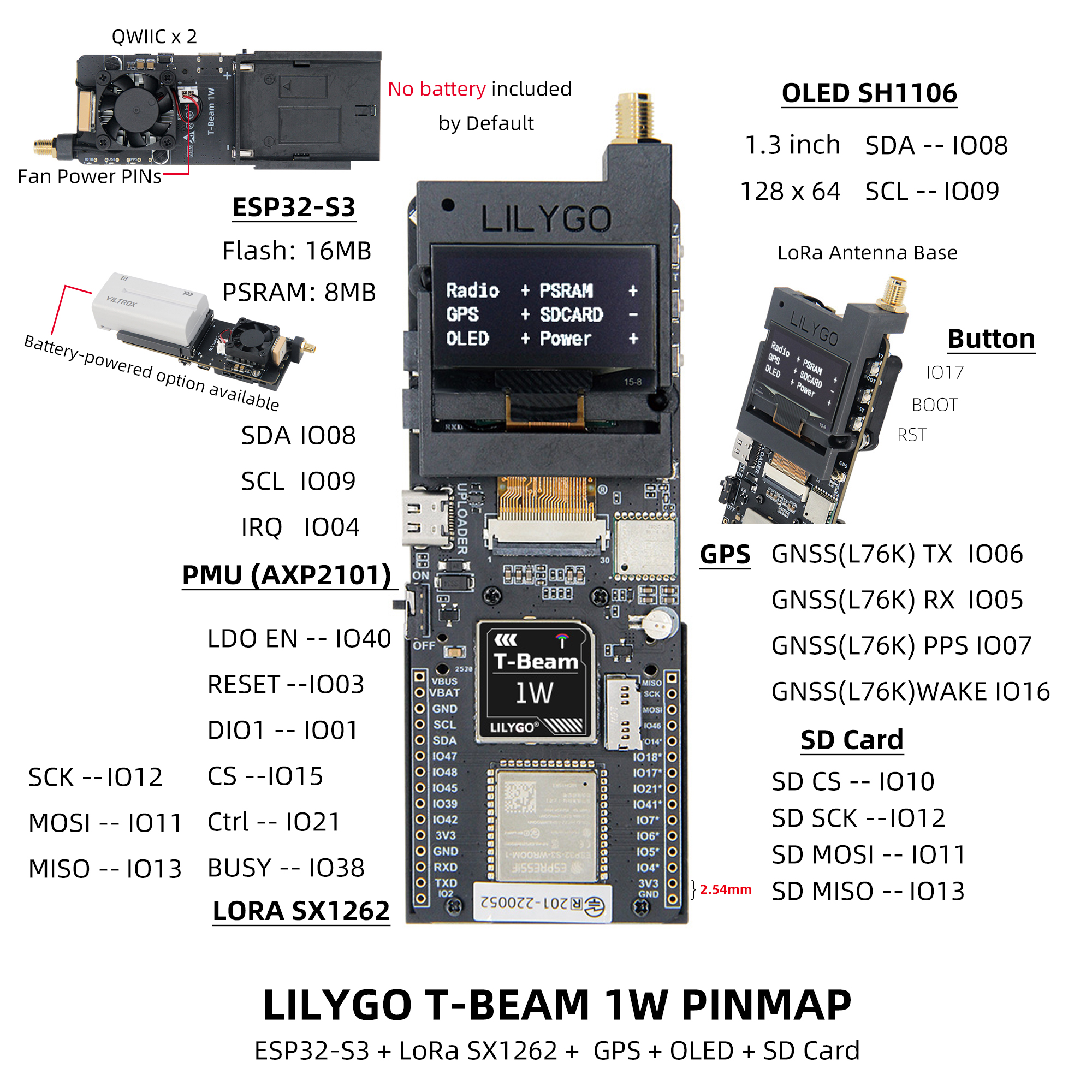
Pin Mapping
| Pin Name | GPIO | Available |
|---|---|---|
| Uart1 TX | 43 | ✅ |
| Uart1 RX | 44 | ✅ |
| I2C SDA | 8 | ❌ |
| I2C SCL | 9 | ❌ |
| SPI MOSI | 11 | ❌ |
| SPI MISO | 12 | ❌ |
| SPI SCK | 13 | ❌ |
| SD CS | 10 | ❌ |
| GPS TX | 6 | ❌ |
| GPS RX | 5 | ❌ |
| GPS PPS | 7 | ❌ |
| GPS Wake-up | 16 | ❌ |
| LoRa RESET | 3 | ❌ |
| LoRa DIO1 | 1 | ❌ |
| LoRa CS | 15 | ❌ |
| LoRa LDO EN | 40 | ❌ |
| LoRa Ctrl | 21 | ❌ |
| LoRa BUSY | 38 | ❌ |
| BOOT Button | 0 | ❌ |
| Custom Button | 17 | ❌ |
| Onboard LED | 18 | ❌ |
| NTC ADC | 14 | ❌ |
| Battery ADC | 4 | ❌ |
| Fan Control | 41 | ❌ |
Note:
- LDO EN is the module internal enable pin, high level turns on Radio.
- LoRa Ctrl is the internal LNA control pin, high level during reception, low level during transmission/sleep.
Electrical Parameters
| Item | Description |
|---|---|
| USB-C Input Voltage | 3.9V ~ 6V |
| Charging Function | Not Supported |
| Battery Voltage | 7.4V |
Tip: Recommended battery discharge capability ≥ 2A, otherwise high-power transmission may trigger protection.
Buttons and LED Description
| Button | Function |
|---|---|
| IO17 | Custom Button |
| BOOT | Download Mode/Custom |
| RST | Reset |
| PWR (Power Button) | Long press 6 seconds to shut down |
| LED | Description |
|---|---|
| IO18 LED | Controlled by GPIO18 |
| PPS LED | Flashes with GPS pulse |
| USB LED | Lights up when USB is connected |
Related Tests
| Band | Module Model | Frequency Range | Output Power | Modulation |
|---|---|---|---|---|
| 868MHz | SX1262 (XY16P35) | 830~950MHz | Max 32dBm | LoRa/FSK/GMSK |
| 433MHz | SX1262 (XY16P354) | 400~520MHz | Max 32dBm | LoRa/FSK/GMSK |
Important Reminders:
- Always connect the antenna before transmission.
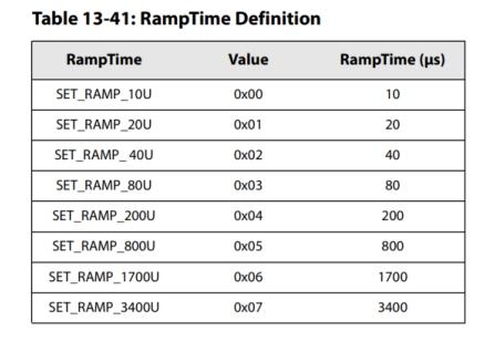
- Recommended PA stabilization time > 800us.
- Switch RF Switch to TX channel in advance before transmission, otherwise PA may be damaged.
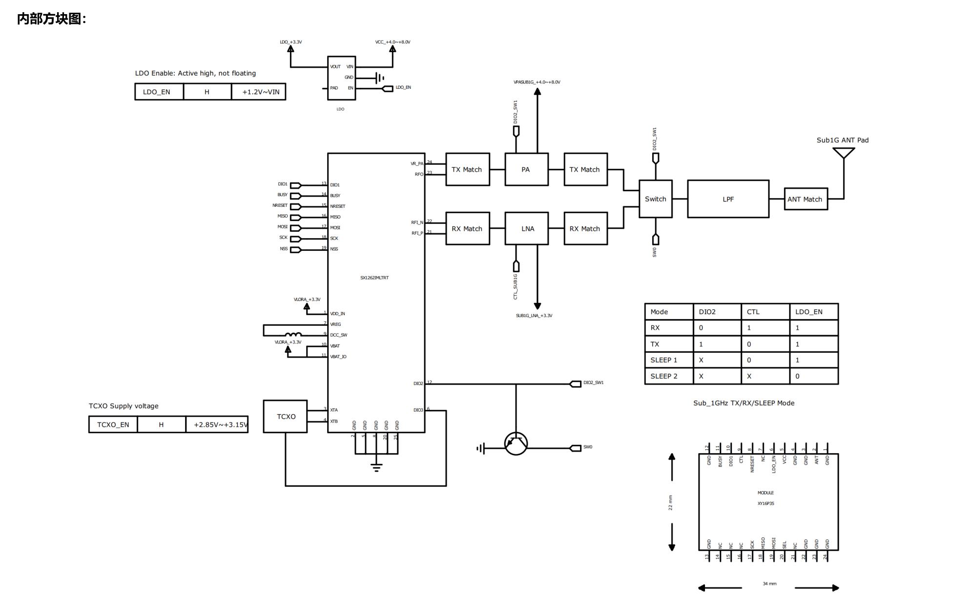
RF Block Diagram
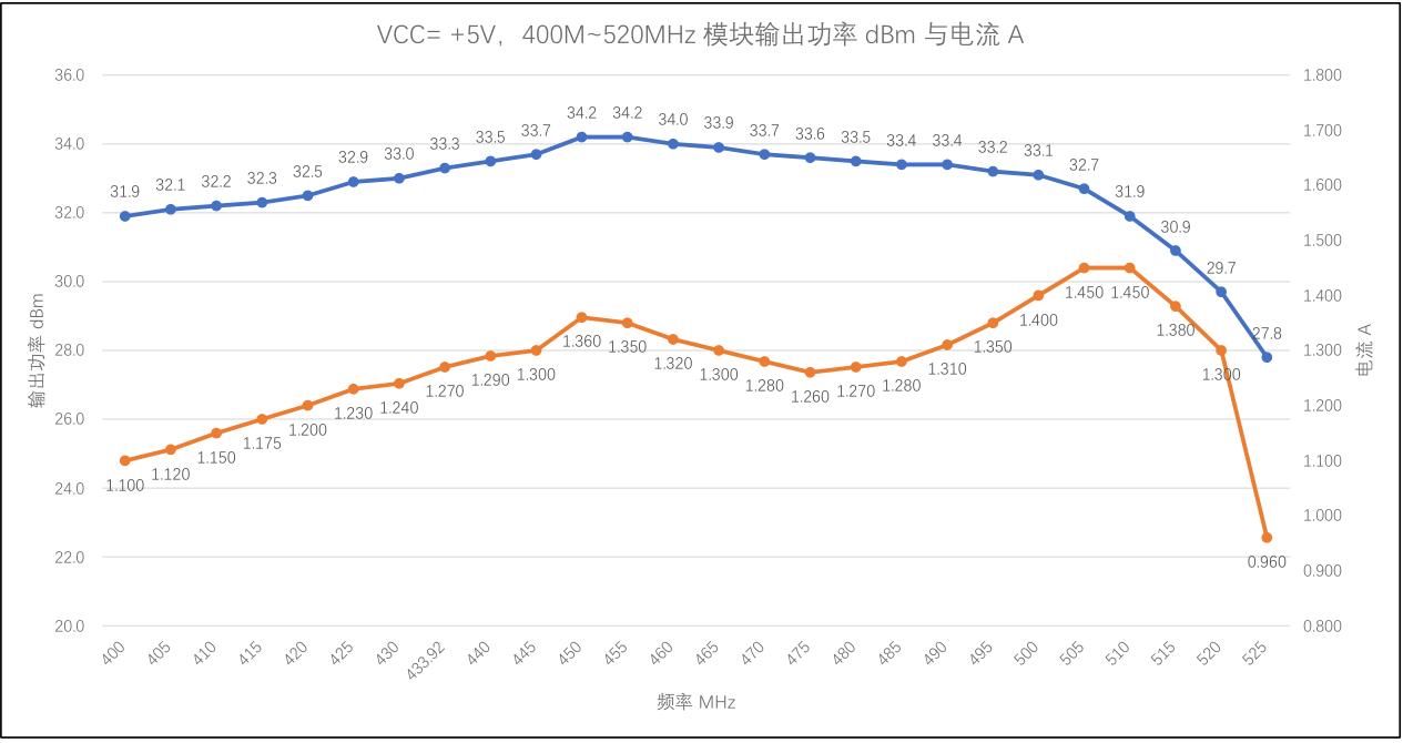
VCC=+5V, 400M~520MHz module output power dBm and current
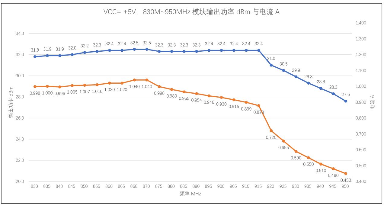
VCC=+5V, 830M~950MHz module output power dBm and current
FAQ
Q. Why does the USB device keep flashing during flashing?
A. Please check if the correct development board model is selected, and ensure the macro definition inutilities.his enabled.Q. Why is the LoRa transmission distance very short?
A. Please confirm that the antenna is connected, RF Switch is correctly switched, and output power is set reasonably.Q. Why does it not power on when using battery power?
A. Please check if the battery voltage is around 7.4V and if the battery discharge capability is sufficient.Q. GPS positioning slow or no signal?
A. Please ensure use in an outdoor open environment and check antenna connection.RF Block Diagram