


 English
LILYGO T3S3
Version History:
| Version | Update date | Update description |
|---|---|---|
| T3S3_V1.2 | Latest Version | Development board integrating ESP32-S3 with multi-band LoRa |
| T3S3_V1.3 | Latest Version | Hardware optimization update |
Purchase Links
| Product | SOC | FLASH | PSRAM | LoRa | Screen | Link |
|---|---|---|---|---|---|---|
| T3S3 | ESP32-S3FH4R2 | 4M | 2M | SX1262/SX1276/SX1280 | 0.96" OLED | LILYGO Mall |
Table of Contents
- Description
- Preview
- Modules
- Quick Start
- Pin Overview
- Related Tests
- FAQ
- Projects
- Resources
- Dependent Libraries
Description
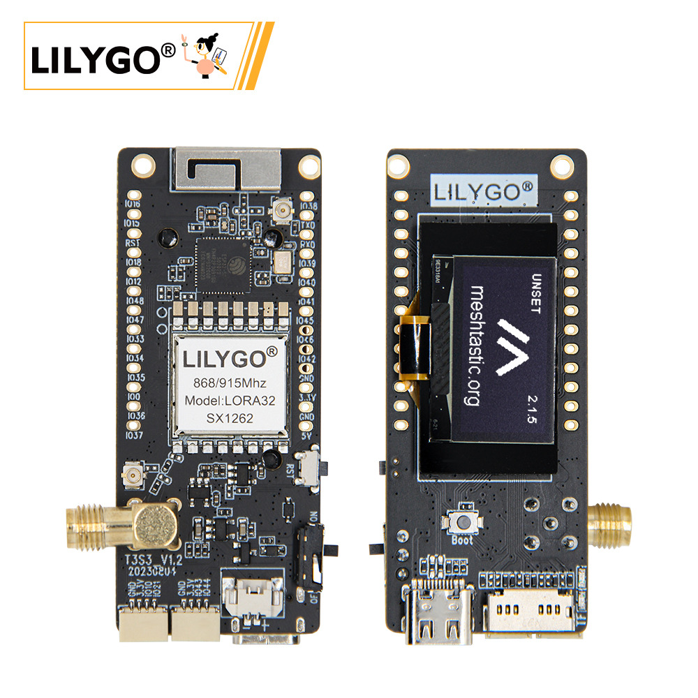
T3S3 (LILYGO T3-S3 V1.2) is a compact development board integrating ESP32-S3 main control with multi-band LoRa communication capability. This development board can be optionally configured with SX1262/1276 (433/868/915MHz) or SX1280 (2.4GHz) LoRa modules, supporting long-distance low-power communication. It features an onboard 0.96-inch 128x64 OLED display (SSD1306) and MicroSD (TF) card slot, providing data visualization and storage functions.
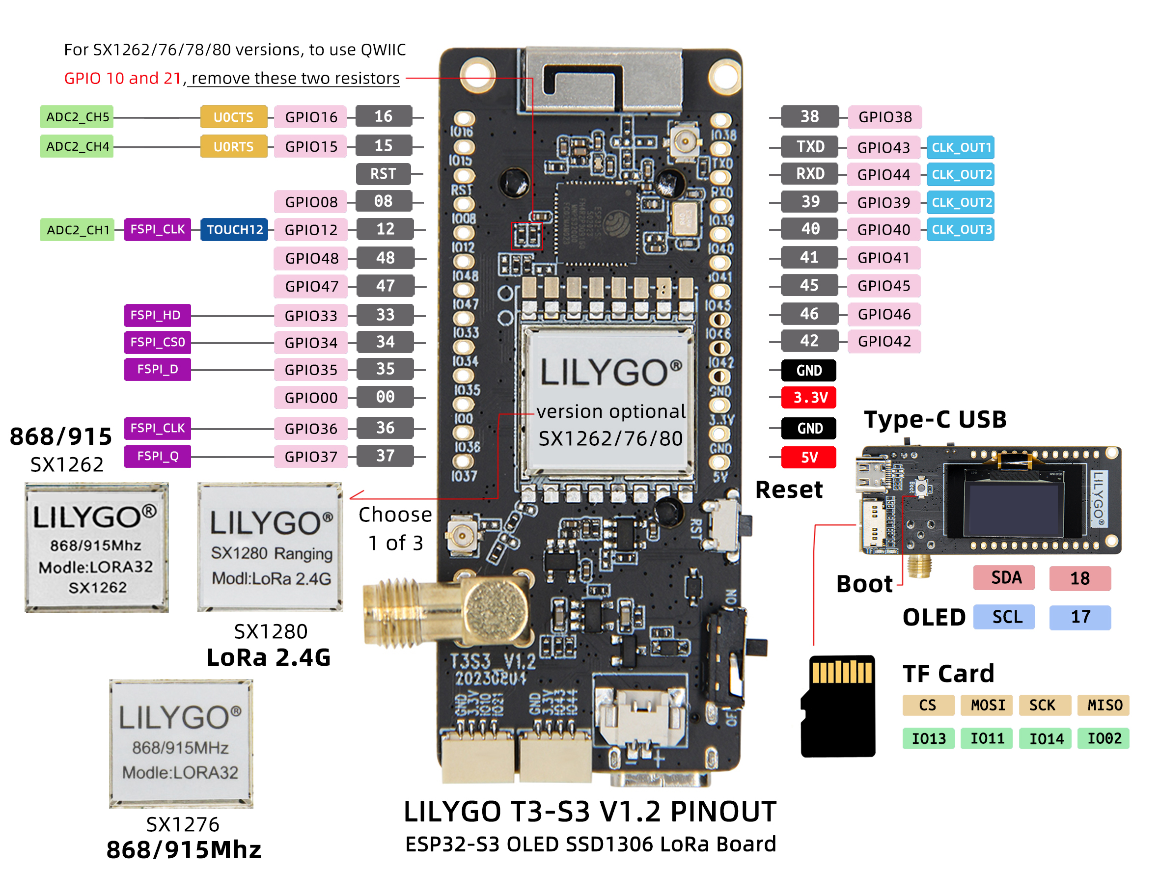
Power supply and program uploading are achieved through Type-C USB, with expanded rich interface resources including ADC (GPIO15/16), UART (U0RTS/U0CTS), PSP bus (GPIO33-37), etc. It also retains BOOT/RST buttons and clearly labeled GPIO pins, suitable for IoT sensor networks, environmental monitoring, and other low-power scenario development.
Preview
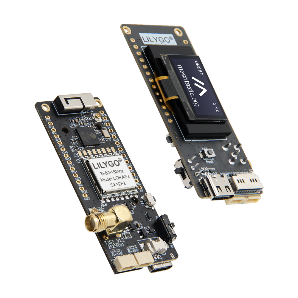
Physical Image
Pin Diagram
Modules
MCU
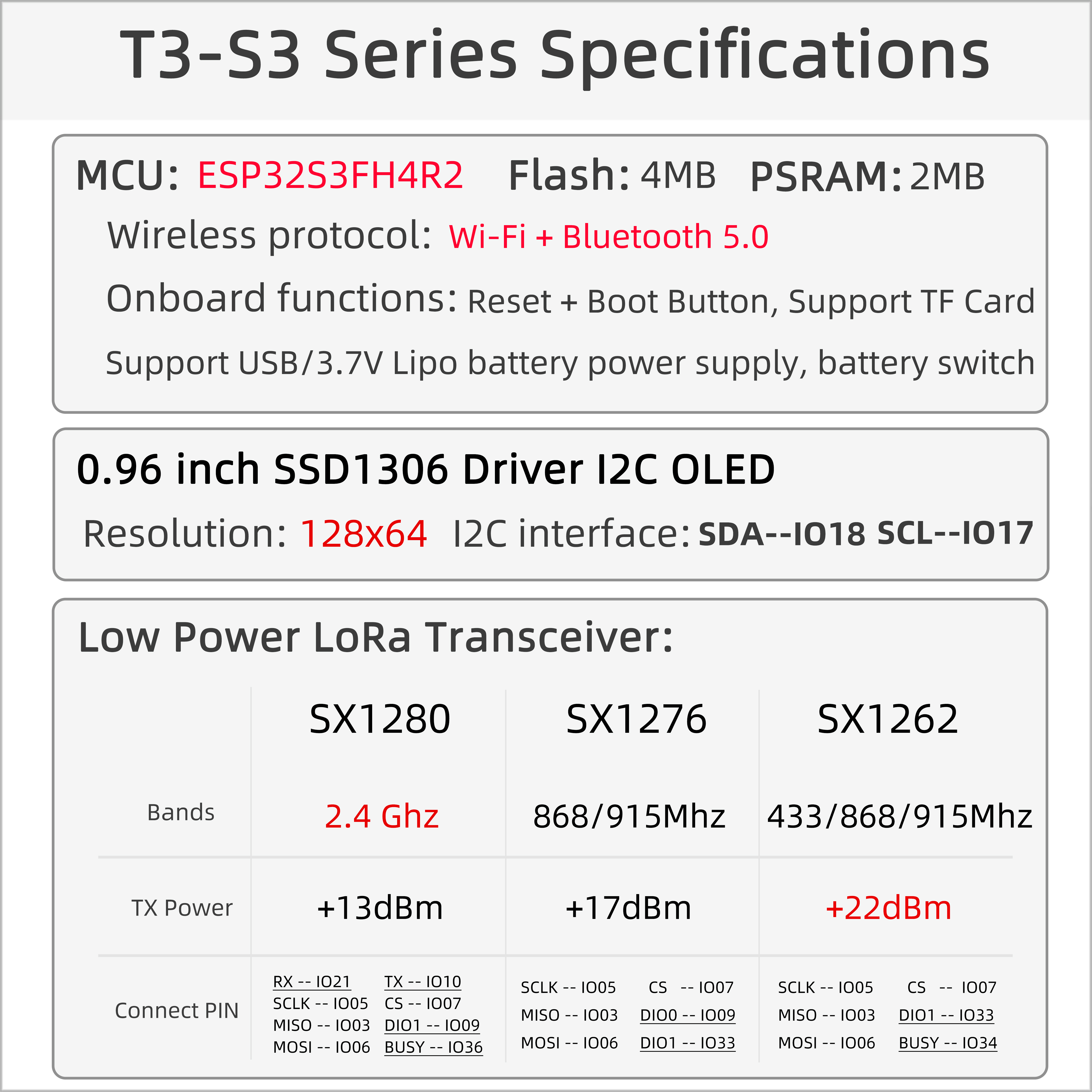
- Chip: ESP32-S3FH4R2
- PSRAM: 2MB (Quad-SPI)
- FLASH: 4MB (Quad-SPI)
- Additional Information: More information available at Espressif Official ESP32-S3 Datasheet
Display
- Size: 0.96-inch OLED
- Resolution: 128x64px
- Display Type: OLED
- Driver Chip: SSD1306
- Bus Communication Protocol: I2C
LoRa
- Chip: SX1262 / SX1276 / SX1280 (optional)
- Frequency: SX1262/SX1276: 433/868/915MHz, SX1280: 2.4GHz
Storage
- Type: MicroSD (TF) Card
- Interface: SPI
Overview
| Component | Description |
|---|---|
| MCU | ESP32-S3FH4R2 |
| FLASH | 4MB (Quad-SPI) |
| PSRAM | 2MB (Quad-SPI) |
| Display | 0.96-inch SSD1306 OLED |
| LoRa | SX1262 (433/868/915MHz) / SX1276 / SX1280 (2.4GHz) |
| Storage | TF Card |
| Wireless | 2.4GHz Wi-Fi + Bluetooth 5.0 |
| USB | 1 × USB Port and OTG (TYPE-C) |
| IO Interface | 2.54mm Pitch 2*13 Expansion IO Interface |
| Expansion Interface | LoRa Antenna Interface + Battery Interface + 2 x Qwiic Interface |
| Buttons | 1 x RESET Button + 1 x BOOT Button |
| Mounting Holes | 2mm Positioning Holes x 2 |
| Dimensions | 66x36x14mm |
Quick Start
Example Support
./examples/
├── ArduinoLoRa                              # Only support SX1276/SX1278 radio module
│   ├── LoRaReceiver
│   └── LoRaSender
├── Display                                  # Only supports TBeam TFT Shield
│   ├── Free_Font_Demo
│   ├── TBeam_TFT_Shield
│   ├── TFT_Char_times
│   └── UTFT_demo
├── GPS                                      # T-Beam GPS demo examples
│   ├── TinyGPS_Example
│   ├── TinyGPS_FullExample
│   ├── TinyGPS_KitchenSink
│   ├── UBlox_BasicNMEARead                  # Only support Ublox GNSS Module
│   ├── UBlox_NMEAParsing                    # Only support Ublox GNSS Module
│   ├── UBlox_OutputRate                     # Only support Ublox GNSS Module
│   └── UBlox_Recovery                       # Only support Ublox GNSS Module
├── LoRaWAN                                  # LoRaWAN examples
│   ├── LMIC_Library_OTTA
│   └── RadioLib_OTAA
├── OLED
│   ├── SH1106FontUsage
│   ├── SH1106GraphicsTest
│   ├── SH1106IconMenu
│   ├── SH1106PrintUTF8
│   ├── SSD1306SimpleDemo
│   └── SSD1306UiDemo
├── PMU                                      # T-Beam & T-Beam S3 PMU demo examples
├── RadioLibExamples                         # RadioLib examples,Support SX1276/78/62/80...
│   ├── Receive_Interrupt
│   └── Transmit_Interrupt
├── Sensor                                   # Sensor examples,only support t-beams3-supreme
│   ├── BME280_AdvancedsettingsExample
│   ├── BME280_TestExample
│   ├── BME280_UnifiedExample
│   ├── PCF8563_AlarmByUnits
│   ├── PCF8563_SimpleTime
│   ├── PCF8563_TimeLib
│   ├── PCF8563_TimeSynchronization
│   ├── QMC6310_CalibrateExample
│   ├── QMC6310_CompassExample
│   ├── QMC6310_GetDataExample
│   ├── QMC6310_GetPolarExample
│   ├── QMI8658_BlockExample
│   ├── QMI8658_GetDataExample
│   ├── QMI8658_InterruptBlockExample
│   ├── QMI8658_InterruptExample
│   ├── QMI8658_LockingMechanismExample
│   ├── QMI8658_MadgwickAHRS
│   ├── QMI8658_PedometerExample
│   ├── QMI8658_ReadFromFifoExample
│   └── QMI8658_WakeOnMotion
|── T3S3Factory                              # T3 S3 factory test examples
└── Factory                                  # T-Beam & T-Beam S3 and BPF factory test examples
PlatformIO
- Install Visual Studio Code.
- Search for and install "PlatformIO IDE" in extensions.
- Download T3S3 project code from GitHub.
- Open the project folder in VS Code, edit the
platformio.inifile to select the desired environment. - Connect the device, compile and upload the program.
Arduino
- Install Arduino IDE
- Install Arduino ESP32
- Copy all folders in the
libdirectory to theSketchbook locationdirectory. To find the library location, refer here- Windows:
C:\Users\{username}\Documents\Arduino - macOS:
/Users/{username}/Documents/Arduino - Linux:
/home/{username}/Arduino
- Windows:
- Open the corresponding example
- Open the downloaded
LilyGo-LoRa-Seriesfolder - Open the
examplesfolder - Select the example file and open the file with the
inoextension
- Open the downloaded
- Select the corresponding development board model in the Arduino IDE Tools menu, click the corresponding option in the list below to select
| Name | Value |
|---|---|
| Board | LilyGo T3-S3 |
| Port | Your port |
| USB CDC On Boot | Enable |
| CPU Frequency | 240MHZ(WiFi) |
| Core Debug Level | None |
| USB DFU On Boot | Disable |
| Erase All Flash Before Sketch Upload | Disable |
| Events Run On | Core1 |
| Arduino Runs On | Core1 |
| USB Firmware MSC On Boot | Disable |
| Partition Scheme | Default 4MB with spiffs (1.2MB APP/1.5MB SPIFFS) |
| PSRAM | QSPI PSRAM |
| Board Revision* | XXXXXX |
| Upload Mode | UART0/Hardware CDC |
| Upload Speed | 921600 |
| USB Mode | CDC and JTAG |
| Programmer | Esptool |
- Board revision Select according to actual model
- Upload the program
Development Platforms
Pin Overview
SX1262
| Name | GPIO NUM | Free |
|---|---|---|
| (QWIIC) Uart1 TX | 43(External QWIIC Socket) | ✅️ |
| (QWIIC) Uart1 RX | 44(External QWIIC Socket) | ✅️ |
| QWIIC Socket IO10* | 10(External QWIIC Socket) | ✅️ |
| QWIIC Socket IO21* | 21(External QWIIC Socket) | ✅️ |
| SDA | 18 | ❌ |
| SCL | 17 | ❌ |
| OLED(SSD1306) SDA | Share with I2C bus | ❌ |
| OLED(SSD1306) SCL | Share with I2C bus | ❌ |
| SD CS | 13 | ❌ |
| SD MOSI | 11 | ❌ |
| SD MISO | 2 | ❌ |
| SD SCK | 14 | ❌ |
| LoRa(SX1262) SCK | 5 | ❌ |
| LoRa(SX1262) MISO | 3 | ❌ |
| LoRa(SX1262) MOSI | 6 | ❌ |
| LoRa(SX1262) RESET | 8 | ❌ |
| LoRa(SX1262) DIO1 | 33 | ❌ |
| LoRa(SX1262) BUSY | 34 | ❌ |
| LoRa(SX1262) CS | 7 | ❌ |
| Button1 (BOOT) | 0 | ❌ |
| Battery ADC | 1 | ❌ |
| On Board LED | 37 | ❌ |
1276
| Name | GPIO NUM | Free |
|---|---|---|
| (QWIIC) Uart1 TX | 43(External QWIIC Socket) | ✅️ |
| (QWIIC) Uart1 RX | 44(External QWIIC Socket) | ✅️ |
| QWIIC Socket IO10* | 10(External QWIIC Socket) | ✅️ |
| QWIIC Socket IO21* | 21(External QWIIC Socket) | ✅️ |
| SDA | 18 | ❌ |
| SCL | 17 | ❌ |
| OLED(SSD1306) SDA | Share with I2C bus | ❌ |
| OLED(SSD1306) SCL | Share with I2C bus | ❌ |
| SD CS | 13 | ❌ |
| SD MOSI | 11 | ❌ |
| SD MISO | 2 | ❌ |
| SD SCK | 14 | ❌ |
| LoRa(SX1276) SCK | 5 | ❌ |
| LoRa(SX1276) MISO | 3 | ❌ |
| LoRa(SX1276) MOSI | 6 | ❌ |
| LoRa(SX1276) RESET | 8 | ❌ |
| LoRa(SX1276) DIO0 | 9 | ❌ |
| LoRa(SX1276) DIO1 | 33 | ❌ |
| LoRa(SX1276) DIO2 | 34 | ❌ |
| LoRa(SX1276) DIO3 | 21 | ❌ |
| LoRa(SX1276) DIO4 | 10 | ❌ |
| LoRa(SX1276) DIO5 | 36 | ❌ |
| LoRa(SX1276) CS | 7 | ❌ |
| Button1 (BOOT) | 0 | ❌ |
| Battery ADC | 1 | ❌ |
| On Board LED | 37 | ❌ |
You can use GPIO10 and GPIO21 by removing the two resistors shown in the figure. Otherwise, this GPIO will default to connecting to the radio's DIO3 and DIO4.
1278
| Name | GPIO NUM | Free |
|---|---|---|
| (QWIIC) Uart1 TX | 43(External QWIIC Socket) | ✅️ |
| (QWIIC) Uart1 RX | 44(External QWIIC Socket) | ✅️ |
| QWIIC Socket IO10* | 10(External QWIIC Socket) | ✅️ |
| QWIIC Socket IO21* | 21(External QWIIC Socket) | ✅️ |
| SDA | 18 | ❌ |
| SCL | 17 | ❌ |
| OLED(SSD1306) SDA | Share with I2C bus | ❌ |
| OLED(SSD1306) SCL | Share with I2C bus | ❌ |
| SD CS | 13 | ❌ |
| SD MOSI | 11 | ❌ |
| SD MISO | 2 | ❌ |
| SD SCK | 14 | ❌ |
| LoRa(SX1278) SCK | 5 | ❌ |
| LoRa(SX1278) MISO | 3 | ❌ |
| LoRa(SX1278) MOSI | 6 | ❌ |
| LoRa(SX1278) RESET | 8 | ❌ |
| LoRa(SX1278) DIO0 | 9 | ❌ |
| LoRa(SX1278) DIO1 | 33 | ❌ |
| LoRa(SX1278) DIO2 | 34 | ❌ |
| LoRa(SX1278) DIO3 | 21 | ❌ |
| LoRa(SX1278) DIO4 | 10 | ❌ |
| LoRa(SX1278) DIO5 | 36 | ❌ |
| LoRa(SX1278) CS | 7 | ❌ |
| Button1 (BOOT) | 0 | ❌ |
| Battery ADC | 1 | ❌ |
| On Board LED | 37 | ❌ |
You can use GPIO10 and GPIO21 by removing the two resistors shown in the figure below. Otherwise, this GPIO will default to connecting to the radio's DIO3 and DIO4 ports.
1280
| Name | GPIO NUM | Free |
|---|---|---|
| Uart1 TX | 43(External QWIIC Socket) | ✅️ |
| Uart1 RX | 44(External QWIIC Socket) | ✅️ |
| QWIIC Socket IO10 | 10(External QWIIC Socket) | ❌ |
| QWIIC Socket IO21 | 21(External QWIIC Socket) | ❌ |
| SDA | 18 | ❌ |
| SCL | 17 | ❌ |
| OLED(SSD1306) SDA | Share with I2C bus | ❌ |
| OLED(SSD1306) SCL | Share with I2C bus | ❌ |
| SD CS | 13 | ❌ |
| SD MOSI | 11 | ❌ |
| SD MISO | 2 | ❌ |
| SD SCK | 14 | ❌ |
| LoRa(SX1280) SCK | 5 | ❌ |
| LoRa(SX1280) MISO | 3 | ❌ |
| LoRa(SX1280) MOSI | 6 | ❌ |
| LoRa(SX1280) RESET | 8 | ❌ |
| LoRa(SX1280) DIO1 | 9 | ❌ |
| LoRa(SX1280) BUSY | 36 | ❌ |
| LoRa(SX1280) CS | 7 | ❌ |
| Button1 (BOOT) | 0 | ❌ |
| Battery ADC | 1 | ❌ |
| On Board LED | 37 | ❌ |
Related Tests
Test data to be completed
FAQ
Q. How to choose LoRa module version?
A. SX1262/SX1276 are suitable for Sub-1GHz bands, with longer communication distance; SX1280 is suitable for 2.4GHz band, with higher data rate.Q. OLED screen not displaying?
A. Check screen ribbon cable connection, confirm I2C address configuration is correct (SSD1306 is usually 0x3C).Q. SD card not recognized?
A. Ensure SD card is correctly formatted (FAT32), check if the card is properly inserted, try different SD cards.Q. Program upload failed?
A. Hold BOOT button and then press RESET to enter download mode, ensure drivers are correctly installed.
Projects
Resources
Dependent Libraries
- RadioLib - LoRa Communication Library
- U8g2 - OLED Display Library
- Arduino_GFX - Graphics Display Library
- SD - SD Card Library