Note: T-Circle S3 is the ESP32-S3 version. Click here to switch to the ESP32 version T-Circle.
Version History:
| Version |
Update Date |
Update Description |
| T-Circle-S3_V1.0 |
2024-01-01 |
Initial Version |
Purchase Link
| Product |
SOC |
FLASH |
PSRAM |
Link |
| T-Circle S3 |
ESP32-S3 |
16M |
8M (Octal SPI) |
LILYGO Mall |
Table of Contents
Description
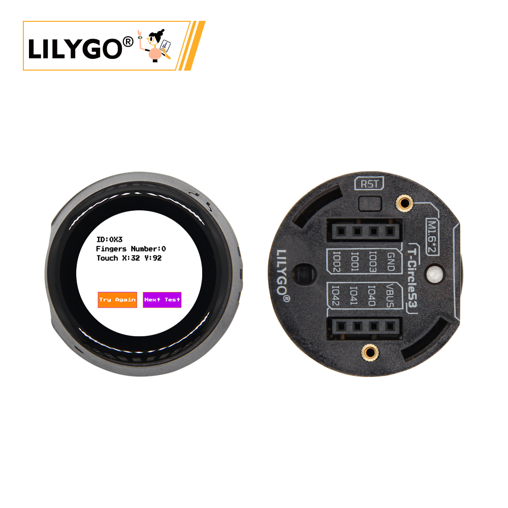
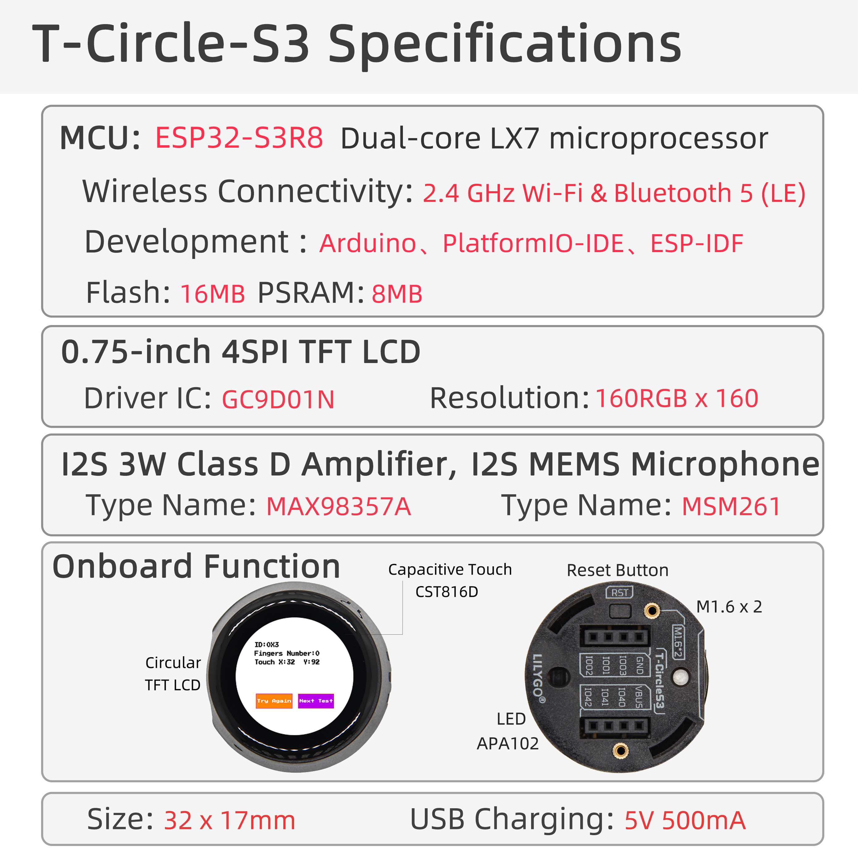
LILYGO T-Circle S3 is a versatile development board based on the ESP32-S3 wireless microcontroller, integrating a 0.75-inch circular LCD touch screen (160x160 pixels), MAX98357A digital audio amplifier, MSM261 audio acquisition module (presumably microphone), APA102 LED control interface, and QWIIC expansion interface. Its core configuration includes 16MB flash memory, 8MB Octal SPI PSRAM, supports Wi-Fi/Bluetooth communication, and features a capacitive touch screen controller CST816D for interactive operation. Through precise pin mapping, it integrates graphic display, audio input/output, touch interaction, and high-speed storage functions, suitable for IoT terminals, smart wearable devices, or prototype development of embedded audio visualization projects.
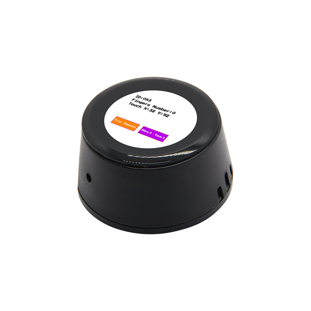
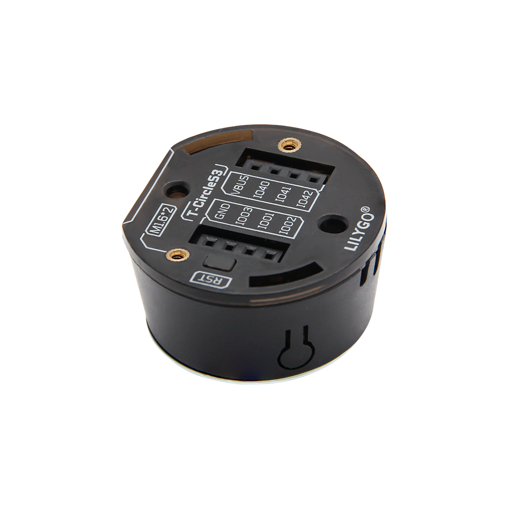
Preview
Physical Images
Pinout Diagram
Modules
1. MCU
2. Screen
- Size: 0.75-inch LCD circular screen
- Resolution: 160x160px
- Type: TFT, LCD
- Driver IC: GC9D01N
- Bus Protocol: Standard SPI
- Related Information:
GC9D01N
TFT_eSPI-2.5.43
- Dependent Libraries:
Arduino_GFX-1.3.7
3. Touch
4. Speaker
5. Microphone
T-Circle-S3_V1.0 Version
T-Circle-S3_V1.1 Version
6. LED Lights
Overview
| Component |
Description |
| MCU |
ESP32-S3-R8 Dual-core LX7 microprocessor |
| FLASH |
16MB |
| PSRAM |
8MB (Octal SPI) |
| Screen |
0.75-inch GC9D01N LCD (160x160) |
| Touch |
CST816D Capacitive Touch Screen |
| Speaker |
I2S driven MAX98357A |
| Microphone |
PDM driven MP34DT05-A |
| LED |
APA102 |
| Wireless |
2.4 GHz Wi-Fi & Bluetooth 5 (LE) |
| USB |
1 × USB Port and OTG (TYPE-C Interface) |
| IO Interface |
2 × 4 pin expansion IO interface |
| Buttons |
1 x RESET button + 1 x BOOT button |
| Power |
5V/500mA |
| Mounting Holes |
2 × M1.6*2 |
| Dimensions |
32*17mm |
Quick Start
Example Support
- Install Visual Studio Code according to your system.
- Open the "Extensions" sidebar in Visual Studio Code (or press Ctrl+Shift+X), search for the "PlatformIO IDE" extension and install it.
- While the extension is installing, download the project from GitHub. You can click the green "<> Code" button to download the main branch, or download a "Releases" version from the sidebar.
- After the extension installation is complete, open the Explorer sidebar (or press Ctrl+Shift+E), click "Open Folder", find the project code you just downloaded (the entire folder), click "Add", and the project files will be added to your workspace.
- Open the "platformio.ini" file in the project folder (PlatformIO should automatically open it after adding the folder). Under the "[platformio]" section, uncomment the line selecting the example program you want to upload (starting with "default_envs = xxx"). Then click the "√" at the bottom left to compile. If the compilation is successful, connect the board to your computer and click the "→" at the bottom left to upload.
Arduino
- Install Arduino IDE according to your system.
- Open the "example" directory in the project folder, select the example project folder, and open the file ending with ".ino" to open the Arduino IDE project workspace.
- Open the "Tools" menu -> "Board" -> "Boards Manager", find or search for "esp32", and install the board files by "Espressif Systems". Then return to the "Board" menu and select the board type under "ESP32 Arduino". The board type to choose is determined by the "board = xxx" header in the "[env]" section of the "platformio.ini" file. If the corresponding board is not available, you need to manually add the board from the "board" directory in the project folder.
- Open the "[File]" -> "[Preferences]" menu, find the "[Sketchbook location]" field. Copy and paste all library files and folders from the "libraries" directory in the project folder into the "libraries" folder at this location.
- Select the correct settings in the "Tools" menu as shown in the table below.
ESP32-S3
| Setting |
Value |
| Board |
ESP32S3 Dev Module |
| Upload Speed |
921600 |
| USB Mode |
Hardware CDC and JTAG |
| USB CDC On Boot |
Enabled |
| USB Firmware MSC On Boot |
Disabled |
| USB DFU On Boot |
Disabled |
| CPU Frequency |
240MHz (WiFi) |
| Flash Mode |
QIO 80MHz |
| Flash Size |
16MB (128Mb) |
| Core Debug Level |
None |
| Partition Scheme |
16M Flash (3MB APP/9.9MB FATFS) |
| PSRAM |
OPI PSRAM |
| Arduino Runs On |
Core 1 |
| Events Run On |
Core 1 |
- Select the correct port.
- Click the "√" in the top right corner to compile. If the compilation is successful, connect the board to your computer and click the "→" to upload.
- Micropython
- Arduino IDE
- Platform IO
Pin Overview
| LCD Screen Pins |
ESP32S3 Pins |
| MOSI |
IO17 |
| DC |
IO16 |
| SCLK |
IO15 |
| CS |
IO13 |
| BL |
IO18 |
| Touch Chip Pins |
ESP32S3 Pins |
| INT |
IO12 |
| SDA |
IO11 |
| SCL |
IO14 |
| Speaker Pins |
ESP32S3 Pins |
| BCLK |
IO5 |
| LRCLK |
IO4 |
| SD_MODE |
IO45 |
| DATA |
IO6 |
| LED Pins |
ESP32S3 Pins |
| CLOCK |
IO39 |
| DATA |
IO38 |
T-Circle-S3_V1.0 Version
| Microphone Pins |
ESP32S3 Pins |
| BCLK |
IO7 |
| WS |
IO9 |
| DATA |
IO8 |
T-Circle-S3_V1.1 Version
| Microphone Pins |
ESP32S3 Pins |
| LRCLK |
IO9 |
| DATA |
IO8 |
(Power consumption and other test data to be added)
FAQ
- Q. I still don't know how to set up the programming environment after reading the above tutorial. What should I do?
A. If you still don't understand how to set up the environment after reading the above tutorial, you can refer to the LilyGo-Document documentation for setup instructions.
- Q. Why does Arduino IDE prompt me to upgrade library files when I open it? Should I upgrade or not?
A. Choose not to upgrade library files. Different versions of library files may not be compatible with each other, so upgrading is not recommended.
- Q. Why is there no serial data output from the "Uart" interface on my board? Is it broken?
A. Because the project file is configured by default to use the USB interface as Uart0 serial output for debugging, and the "Uart" interface is connected to Uart0, it won't output any data without configuration.
PlatformIO users: Open the project file "platformio.ini", change the option "-DARDUINO_USB_CDC_ON_BOOT=true" under "build_flags = xxx" to "-DARDUINO_USB_CDC_ON_BOOT=false" to use the external "Uart" interface normally.
Arduino users: Open the "Tools" menu, select USB CDC On Boot: "Disabled" to use the external "Uart" interface normally.
- Q. Why does my board keep failing to upload programs?
A. Please hold down the "BOOT-0" button and try uploading again.
Projects
Resources
Dependent Libraries


 English