Version History
| Version |
Update date |
Update description |
| T3-S3-LR1121_V1.3 |
2024-03-25 |
Initial hardware version |
| T3-S3-LR1121_V1.4 |
2024-06-18 |
Software optimization update |
Purchase Links
| Product |
SOC |
FLASH |
PSRAM |
Link |
| T3-S3 LR1121 |
ESP32-S3 |
4MB |
2MB |
LILYGO Store |
Table of Contents
Description
LILYGO T3-S3 LR1121 is a highly integrated IoT development board based on ESP32-S3, supporting dual-band LoRa communication at 2.4GHz and 830-945MHz, covering long-distance transmission requirements (10km+), and compatible with spectrum regulations in different regions worldwide. The onboard 1.3-inch OLED screen displays data in real-time, equipped with a TF card slot for storage expansion, and a Type-C interface simplifies power supply and debugging. It provides abundant GPIO pins (supporting ADC, SPI, I2C, and other protocols), allowing flexible connection of sensors or peripherals. Combined with Wi-Fi/Bluetooth 5.0, it enables multi-protocol interconnection. Suitable for smart agriculture monitoring, industrial equipment management, emergency communication networks, and smart home gateways, it balances low-power design with a compact structure, making it an ideal hardware platform for efficiently building IoT systems.
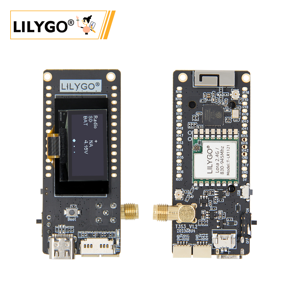
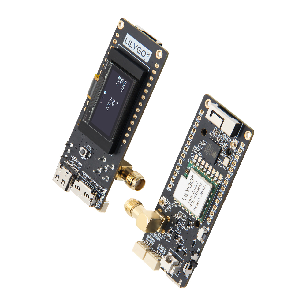
Preview
Physical Image
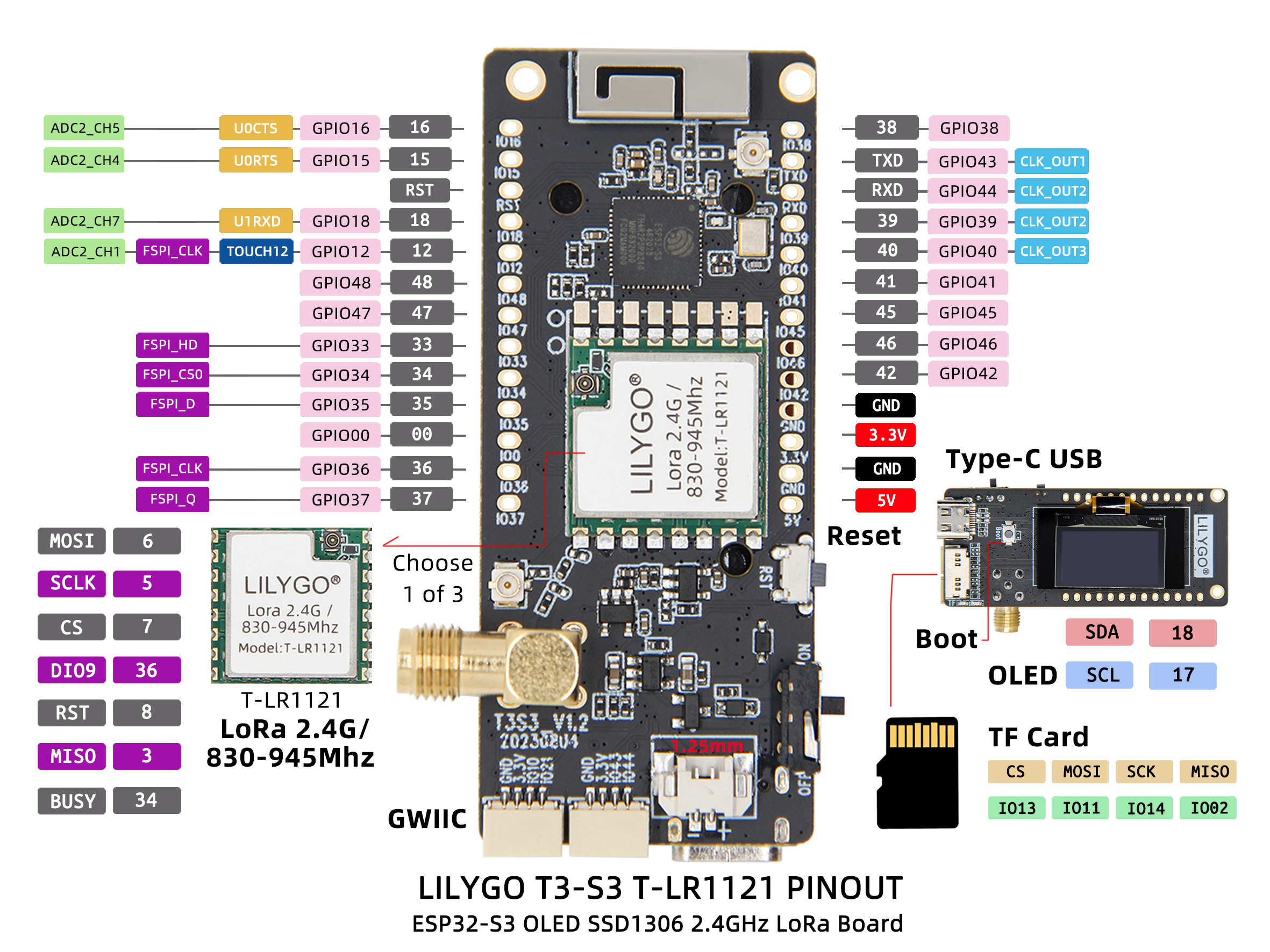
Pin Diagram
Modules
MCU
- Chip: ESP32-S3FH4R2
- PSRAM: 2MB (QSPI PSRAM)
- FLASH: 4MB
- Wireless: 2.4GHz Wi-Fi + Bluetooth 5.0
Display
- Size: 1.3-inch OLED display
- Interface: I2C
- Driver: Standard OLED driver
Wireless Communication
- LoRa Chip: LR1121
- Frequency Band: 830-945MHz + 2.4GHz dual-band
- Communication Distance: 10km+ (ideal conditions)
Power Management
- RTC: PCF85063ATL Real-time Clock
- Power Supply: 5V/500mA
- Battery Interface: 1.25mm battery interface
Overview
| Component |
Description |
| MCU |
ESP32-S3FH4R2 Dual-core LX7 |
| FLASH |
4MB |
| PSRAM |
2MB |
| Display |
1.3-inch I2C OLED |
| LoRa |
LR1121 Dual-band (830-945MHz + 2.4GHz) |
| RTC |
PCF85063ATL Real-time Clock (I2C) |
| Storage |
TF Card Expansion |
| Wireless |
2.4GHz Wi-Fi + Bluetooth 5.0 |
| USB |
1 × USB Port (TYPE-C) |
| Expansion Interface |
2 × QWIIC Interface |
| GPIO Interface |
2.54mm Pitch 2×20 Expansion IO Interface |
| Battery Interface |
1.25mm Battery Interface |
| Buttons |
1 x RESET Button + 1 x BOOT Button |
| Power Input |
5V/500mA |
| Mounting Holes |
2 × 2mm Positioning Holes |
| Dimensions |
66 × 27 × 15 mm |
Quick Start
Example Support
- Install Visual Studio Code and Python
- Search for the
PlatformIO extension in Visual Studio Code and install it
- After installation, restart
Visual Studio Code
- After restarting, select
File -> Open Folder in the top left corner -> choose the LilyGo-LoRa-Series directory
- Wait for third-party dependency libraries to install
- Click to open the
platformio.ini file, under the platformio section
- Select the development board name you want to use under
default_envs and uncomment it
- Uncomment one line of
src_dir = xxxx, ensuring only one line is active. Please note the example comments which explain which features are available and which are not.
- Click the (✔) symbol at the bottom left to compile
- Connect the development board to the computer using a USB-C cable (Micro-USB interface is for module firmware upgrade)
- Click (→) to upload the firmware
- Click (plug symbol) to monitor serial output
- If unable to upload or USB device keeps blinking, please check the FAQ below
Arduino
- Install Arduino IDE
- Install Arduino ESP32
- Copy all folders in the
lib directory to the Sketchbook location directory. To find the library location, refer here
- Windows:
C:\Users\{username}\Documents\Arduino
- macOS:
/Users/{username}/Documents/Arduino
- Linux:
/home/{username}/Arduino
- Open the corresponding example
- Open the downloaded
LilyGo-LoRa-Series folder
- Open the
examples folder
- Select the example file and open the file with the
ino extension
- Select the corresponding development board model in the Arduino IDE Tools menu, click the corresponding option in the list below to select
| Name |
Value |
| Board |
LilyGo T3-S3 |
| Port |
Your port |
| USB CDC On Boot |
Enable |
| CPU Frequency |
240MHZ(WiFi) |
| Core Debug Level |
None |
| USB DFU On Boot |
Disable |
| Erase All Flash Before Sketch Upload |
Disable |
| Events Run On |
Core1 |
| Arduino Runs On |
Core1 |
| USB Firmware MSC On Boot |
Disable |
| Partition Scheme |
Default 4MB with spiffs (1.2MB APP/1.5MB SPIFFS) |
| PSRAM |
QSPI PSRAM |
| Board Revision* |
Radio-LR1121 |
| Upload Mode |
UART0/Hardware CDC |
| Upload Speed |
921600 |
| USB Mode |
CDC and JTAG |
| Programmer |
Esptool |
- Board Revision please select according to the actual model
- Upload the program
- Micropython
- Arduino IDE
- Platform IO
- VS Code
Pin Overview
| Name |
GPIO NUM |
Free |
| (QWIIC) Uart1 TX |
43(External QWIIC Socket) |
✅️ |
| (QWIIC) Uart1 RX |
44(External QWIIC Socket) |
✅️ |
| QWIIC Socket IO10* |
10(External QWIIC Socket) |
✅️ |
| QWIIC Socket IO21* |
21(External QWIIC Socket) |
✅️ |
| SDA |
18 |
❌ |
| SCL |
17 |
❌ |
| OLED(SSD1306) SDA |
Share with I2C bus |
❌ |
| OLED(SSD1306) SCL |
Share with I2C bus |
❌ |
| SD CS |
13 |
❌ |
| SD MOSI |
11 |
❌ |
| SD MISO |
2 |
❌ |
| SD SCK |
14 |
❌ |
| LoRa(LR1121) SCK |
5 |
❌ |
| LoRa(LR1121) MISO |
3 |
❌ |
| LoRa(LR1121) MOSI |
6 |
❌ |
| LoRa(LR1121) RESET |
8 |
❌ |
| LoRa(LR1121) DIO9 |
36 |
❌ |
| LoRa(LR1121) BUSY |
34 |
❌ |
| LoRa(LR1121) CS |
7 |
❌ |
| Button1 (BOOT) |
0 |
❌ |
| Battery ADC |
1 |
❌ |
| On Board LED |
37 |
❌ |
| Frequency Band |
Communication Distance |
Data Rate |
| 830-945MHz |
10km+ |
0.3-50 kbps |
| 2.4GHz |
2km+ |
0.3-50 kbps |
| Features |
Details |
| 🔗USB-C Input Voltage |
5V |
| 🔗Solar Input Voltage(T3 V1.3 Only) |
4.5~5.6V |
| ⚡Charge Current |
500mA |
| 🔋Battery Voltage |
3.7V |
| 🔋Battery Socket Cables |
PH2.0mm |
| 🔗QWIIC Socket Cables |
JST1.0 |
| Features |
Details |
| RF Module |
LR1121 |
| Frequency range |
400-520MHz/830-945MHz/2400-2500MHz |
| Transfer rate(LoRa Sub1G) |
0.018 K ~ 62.5 Kbps |
| Transfer rate(FSK Sub1G) |
0.6 K ~ 300 Kbps |
| Transfer rate(LoRa 2.4G) |
0.476 K~101.5 Kbps |
| Modulation |
LoRa,FSK,LR-HFSS |
FAQ
Q. How to adjust the external antenna resistor?
A. Refer to the image below to adjust the resistor direction for the external antenna:

Q. What advantages does LR1121 have over traditional LoRa chips?
A. LR1121 supports dual-band (Sub-GHz + 2.4GHz), providing greater deployment flexibility and better anti-interference capability.
Q. Can dual bands work simultaneously?
A. LR1121 supports band switching but cannot transmit and receive data on different bands simultaneously.
Q. What factors affect communication distance?
A. Communication distance is affected by environmental obstacles, antenna gain, transmission power, data rate, and other factors.
Q. Why does my board fail to upload programs?
A. Please hold down the "BOOT" button and press the "RST" button simultaneously, then release the "RST" button to enter download mode, and try uploading the program again.
Projects
Resources
Dependent Libraries


 English