


 English
LILYGO T-Glass
Version History
| Product(PinMap) | SOC | Flash | PSRAM | Resolution | Visible Area |
|---|---|---|---|---|---|
| T-Glass/V2 | ESP32-S3 FN4R2 | 4MB | 2MB(QSPI) | 294x126 | 126x126 |
| T-Wristband | ESP32-S3 FN4R2 | 4MB | 2MB(QSPI) | 294x126 | 126x250 |
| Current consumption | Working current | Sleep current | Sleep mode |
|---|---|---|---|
| T-Glass/V2 | (240MHz) WiFi On 90~230+ mA | about 300uA | touch button wakeup |
| T-Wristband | (240MHz) WiFi On 90~230+ mA | about 300uA | touch button wakeup |
Purchase Links
| Product | SOC | FLASH | PSRAM | Link |
|---|---|---|---|---|
| T-Glass | ESP32-S3 | 4MB | 2MB | LILYGO Store |
| T-Wristband | ESP32-S3 | 4MB | 2MB | LILYGO Store |
Table of Contents
- Description
- Preview
- Modules
- Quick Start
- Pin Overview
- Related Tests
- FAQ
- Projects
- Resources
- Dependent Libraries
Description
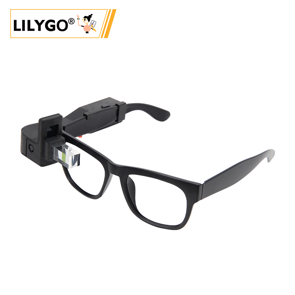
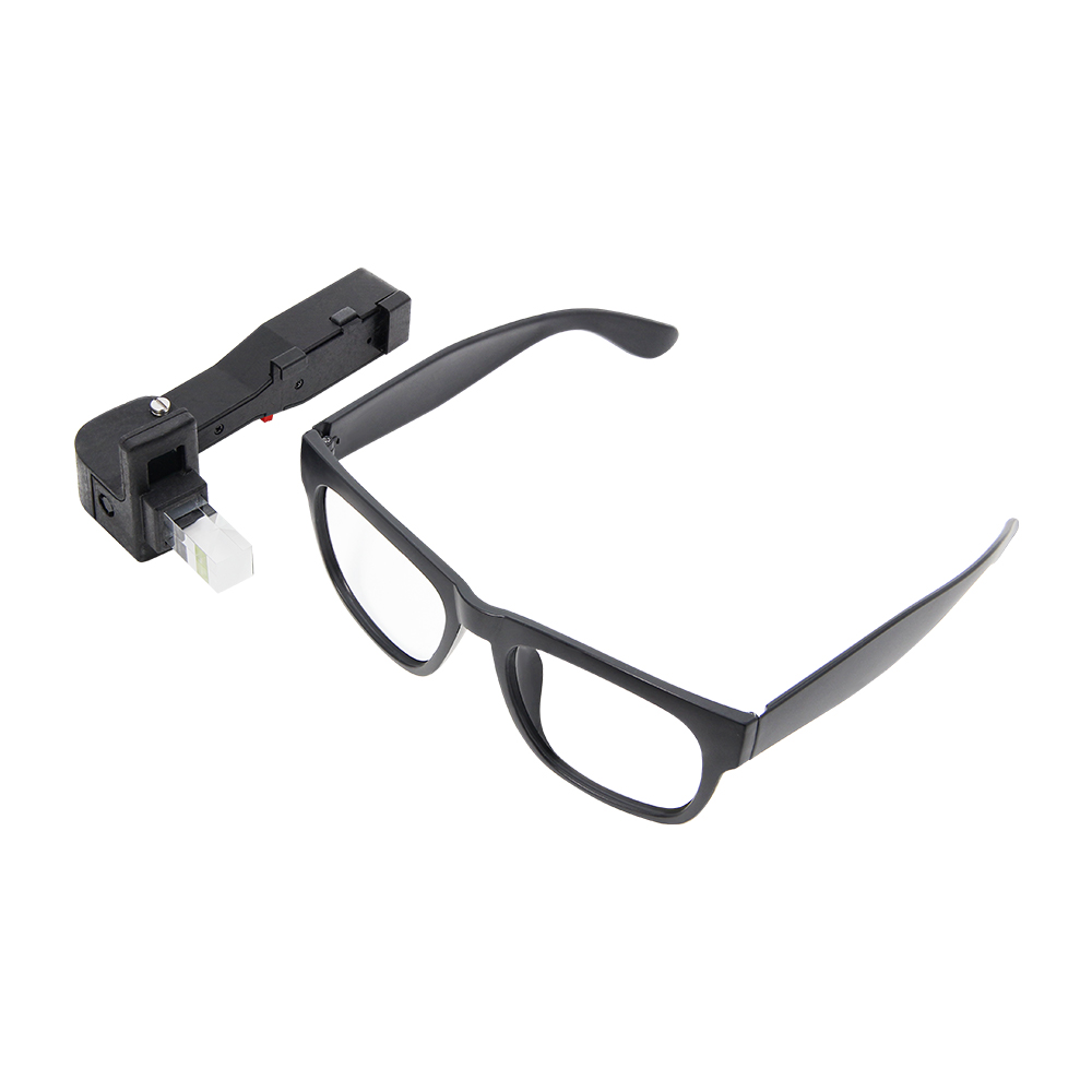
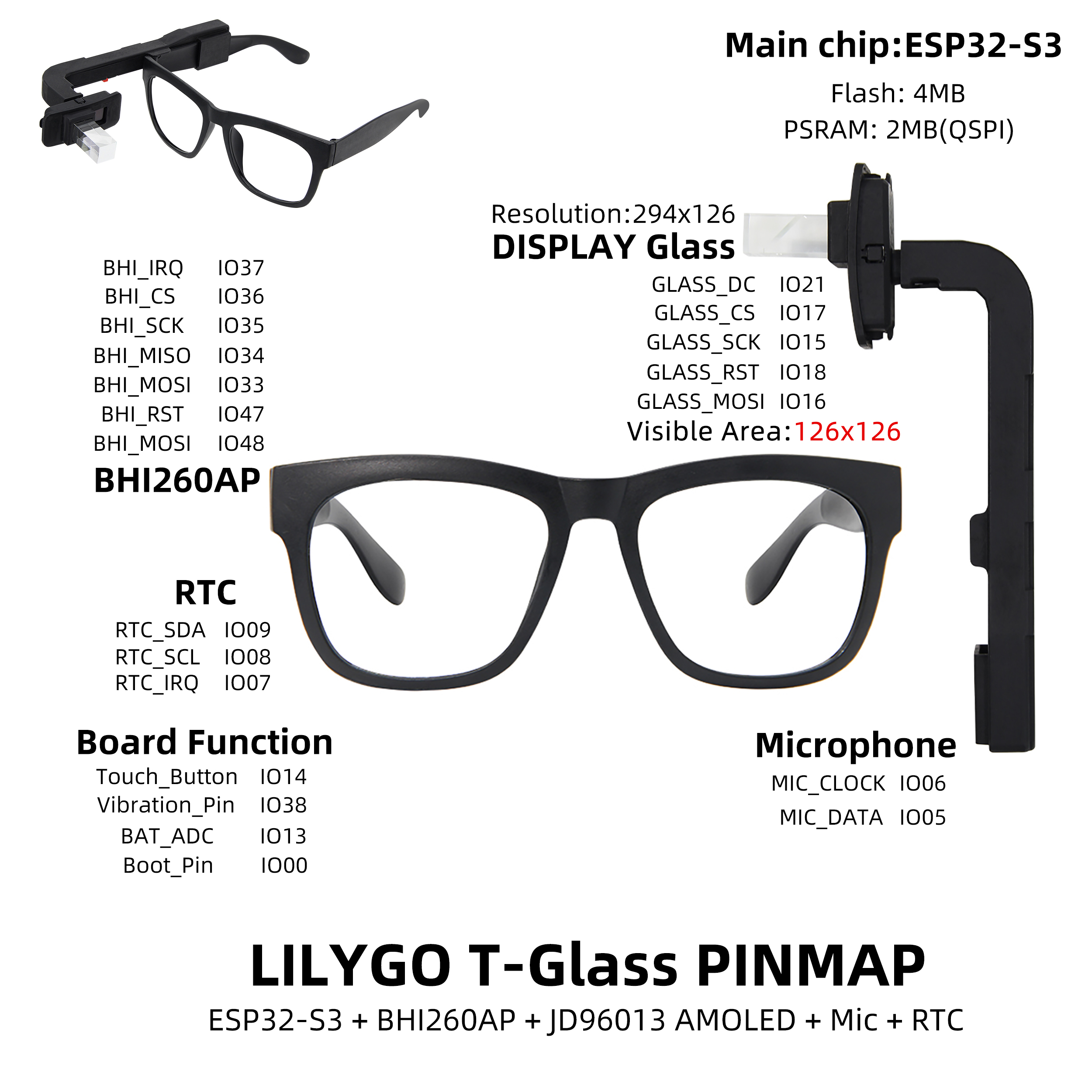
LILYGO T-Glass is a smart wearable device based on the ESP32-S3 main control chip, integrating BHI260AP motion sensor and JD96013A model AMOLED display with a 126×126 pixel visible display area, supporting touch interaction and high contrast visual effects. Built-in 4MB Flash and 2MB OSPI PSRAM ensure smooth operation and data storage capabilities. Rich functional modules include real-time clock (RTC), microphone (supporting MIC_CLOCK/MIC_DATA audio input), vibration feedback (Vibration_Pin), battery level monitoring (BAT_ADC), and touch buttons (Touch_Button), suitable for motion tracking, smart notifications, and other scenarios. Through the LILYGOT-GlassPINMAP interface solution, it integrates communication protocols such as SPI, I²C, optimizes hardware layout, suitable for lightweight design requirements like smart glasses or portable wearable devices, combining low power consumption with high performance characteristics.
Preview
Physical Image
Pinout Diagram
Modules
MCU
- Chip: ESP32-S3 FN4R2
- PSRAM: 2MB (QSPI PSRAM)
- FLASH: 4MB
- Wireless: 2.4 GHz Wi-Fi & Bluetooth 5 (LE)
Display
- Size: 1.1-inch LTPS AMOLED screen
- Resolution: 294×126px
- Display Type: LTPS AMOLED
- Driver IC: JD9613
- Compatible Libraries: LVGL
- Bus Communication Protocol: SPI
Motion Sensor
- Chip: BHI260AP
- Function: AI smart motion sensing
Audio System
- Function: Microphone input
- Interface: MIC_CLOCK/MIC_DATA
Power Management
- Battery: Lithium polymer battery
- Monitoring: Battery level monitoring (ADC)
Overview
| Component | Description |
|---|---|
| MCU | ESP32-S3 FN4R2 |
| FLASH | 4MB |
| PSRAM | 2MB |
| Display | 1.1-inch JD9613 LTPS AMOLED |
| Motion Sensor | BHI260AP AI Smart Sensor |
| Touch | Side touch button |
| RTC | PCF85063A Real-time Clock |
| Audio | Microphone input |
| Vibration | Vibration feedback motor |
| Wireless | 2.4 GHz Wi-Fi & Bluetooth 5 (LE) |
| USB | 1 × USB Port (TYPE-C Interface) |
| Expansion Interface | 2 × QWIIC 4 pin interface |
| Buttons | 1 x RESET Button + 1 x BOOT Button |
| Switch | Side power switch |
| Dimensions | 140 × 67 × 111 mm |
Quick Start
Example Support
./examples/
├── Glass                  # Initial version
│   ├── Glass6DoF
│   ├── GlassBatteryVoltage
│   ├── GlassDeepSleep
│   ├── GlassDisplayRotation
│   ├── GlassFactory
│   │   └── src
│   ├── GlassHelloWorld
│   ├── GlassRtcAlarm
│   ├── GlassRtcDateTime
│   ├── GlassTouchButton
│   ├── GlassTouchButtonEvent
│   └── GlassVoiceActivityDetection
├── GlassV2                # Modify the reflective prism version
│   ├── Glass6DoF
│   ├── GlassBatteryVoltage
│   ├── GlassDeepSleep
│   ├── GlassFactory
│   │   └── src
│   ├── GlassHelloWorld
│   ├── GlassRtcAlarm
│   ├── GlassRtcDateTime
│   ├── GlassTouchButton
│   ├── GlassTouchButtonEvent
│   └── GlassVoiceActivityDetection
└── Wristband
    ├── Wristband6DoF
    ├── WristbandBatteryVoltage
    ├── WristbandDeepSleep
    ├── WristbandDisplayRotation
    ├── WristbandDisplayVisualWindow1
    ├── WristbandFactory
    │   └── src
    ├── WristbandHelloWorld
    ├── WristbandLightSleep
    ├── WristbandRtcAlarm
    ├── WristbandRtcDateTime
    ├── WristbandTouchButton
    └── WristbandTouchButtonEvent
PlatformIO
- Install Visual Studio Code and Python (Python 3.8+ is recommended)
- Search for the
PlatformIOplugin in the Visual Studio Code extension store and install it - After installation, restart Visual Studio Code
- After restarting Visual Studio Code, click the upper left corner of the software's "File" → "Open Folder" → select the project directory of "LilyGO T-Wristband and T-Glass"
- Wait for the automatic installation of third-party dependency libraries to complete (it may take a few minutes on the first opening)
- Click on the configuration file
platformio.iniin the project opened, find theplatformioconfiguration section - Remove the comment of one line
src_dir = xxxx(delete the line's leading;), ensure only one effective configuration is retained (select the corresponding directory according to the target development board) - Click the (✔) icon at the lower left corner of the software to start compiling the project
- Connect the development board to the computer via USB cable
- Click the (→) icon to upload the firmware to the development board
- Click the (plug icon) to open the serial port monitor to view the device's output logs
- If there are issues such as inability to write the firmware or the USB device constantly flashing, please refer to the Frequently Asked Questions (FAQ) below
Arduino
Install Arduino IDE
Install Arduino ESP32 V 2.0.5 or above and below V3.0, Library based on the Stable version, Please make sure the link in Boards Manager is
https://espressif.github.io/arduino-esp32/package_esp32_index.jsonSketch->Include Library->Manage LibrariesLibrary Search->LilyGO T-Wristband and T-Glass->Install->Install ALLLibrary Search->lvgl->v8.4.0->InstallLibrary Search->SensorLib->v0.1.8->InstallFile->Examples->LilyGO T-Wristband and T-Glass->Select the corresponding exampleTools-> , Make your selection according to the table below
| Arduino IDE Setting | Value |
| ------------------------------------ | ------------------------------------------------- |
| Board | ESP32S3 Dev Module |
| Port | Your port |
| USB CDC On Boot | Enable |
| CPU Frequency | 240MHZ(WiFi) |
| Core Debug Level | None |
| USB DFU On Boot | Disable |
| Erase All Flash Before Sketch Upload | Disable |
| Events Run On | Core1 |
| Flash Mode | QIO 80MHZ |
| Flash Size | 4MB(32Mb) |
| Arduino Runs On | Core1 |
| USB Firmware MSC On Boot | Disable |
| Partition Scheme | Default 4M with spiffs(1.2M APP/1.5MB SPIFFS) |
| PSRAM | QSPI PSRAM |
| Upload Mode | UART0/Hardware CDC |
| Upload Speed | 921600 |
| USB Mode | CDC and JTAG |- The options in bold are required, others are selected according to actual conditions.
Select
PortClick
upload, Wait for compilation and writing to completeIf it cannot be written, or the USB device keeps flashing, please check the FAQ below
Development Platforms
Related Tests
Q&A
This development board uses USB as the JTAG upload port. If you need to print serial port information via USB, you must enable the "USB_CDC_ON_BOOT" configuration.
If you cannot find the port when uploading the program, or the USB is used for other functions causing the port not to be displayed, please manually enter the upload mode:- Connect the development board via a USB cable
- Press and hold the "BOOT button" and simultaneously press the "RST button"
- Release the "RST button" first
- Then release the "BOOT button"
- Upload the program
If the above methods do not work, please burn the binary fileto check if the hardware is functioning properly.
If an external power supply is used instead of USB-C power supply, please disable the USB_CDC_ON_BOOT option. This is because the development board waits for USB connection upon startup.
- For Arduino IDE users, you can disable this function in the options. Please note that disabling USB_CDC_ON_BOOT will disable the USB-C serial port redirection. At this point, opening the port via USB-C will not display any serial port information. The information will be output from GPIO43 and GPIO44:
Tools -> USB CDC On Boot -> Disable
- For Platformio users, you can add the following compilation flags in the ini file:
    build_flags =
    ; Enabling -DARDUINO_USB_CDC_ON_BOOT will start printing and wait for the terminal to connect during startup. ; -DARDUINO_USB_CDC_ON_BOOT=1

    ; Enabling -UARDUINO_USB_CDC_ON_BOOT will disable the printing function and will not cause any blocking when powered by a battery. -UARDUINO_USB_CDC_ON_BOOT
- The RAM of the JD9613 display is only half the size of the screen, and it does not support rotation. Direction 0 and 1 can adjust the vertical direction, while directions 1 and 3 are in the same direction:
// Set the screen to landscape mode. 0 and 2 represent two opposite vertical directions. amoled.setRotation(0);
amoled.setRotation(2);

// Set the screen to landscape mode, with directions 1 and 3 being the same and unable to be changed. amoled.setRotation(1);
amoled.setRotation(3);
project
| Product(PinMap) | schematic |
|---|---|
| T-Glass | schematic |
| T-Wristband | schematic |