


 English
LILYGO T5 E-Paper S3 Pro
Version Iteration:
| ID | Hardware | Software | Remark |
|---|---|---|---|
| H752-01 | v1.0-241224 | v1.2_250118 | latest |
| H752 | v1.0-240810 | v1.0-241203 | - |
H752-01 New Version:
- Added E-Ink display power management chip TPS65185;
- Supports partial refresh, adjustable Vcom voltage for display color depth control;
- Supports epdiy v7 direct drive.
- Added GPS module;
Purchase Links
| Product | SOC | FLASH | PSRAM | Link |
|---|---|---|---|---|
| T5-4.7-S3 Epaper PRO | ESP32-S3-WROOM-1 | 16MB | 8MB | LILYGO Mall |
Table of Contents
- Description
- Preview
- Modules
- Quick Start
- Pin Overview
- Related Tests
- FAQ
- Projects
- Resources
- Dependent Libraries
Description
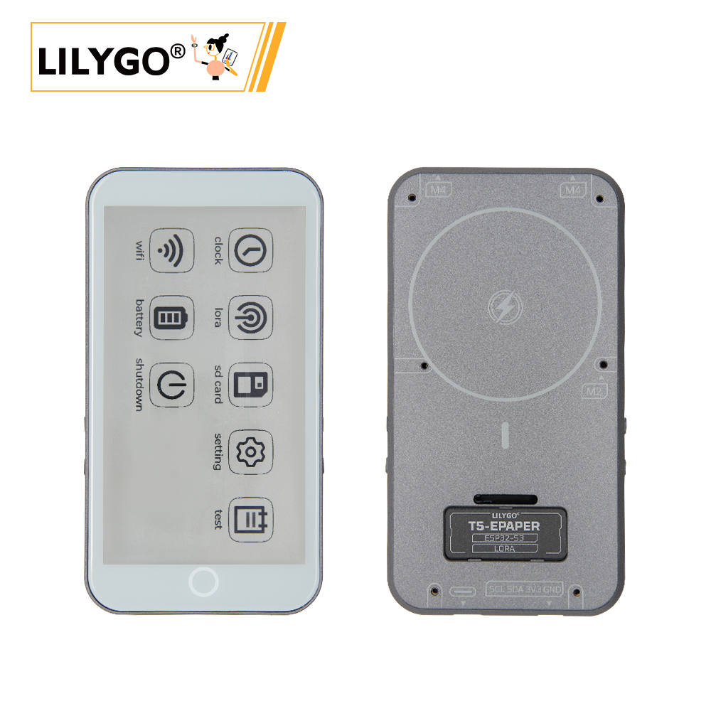
T5-4.7-S3 Epaper PRO is a multifunctional IoT device based on the ESP32-S3-WROOM-1 main control chip (8MB PSRAM + 16MB FLASH), integrating LoRa SX1262 long-range communication module, 4.7-inch E-Ink display (low-power persistent display) and capacitive touchscreen (supporting two-point touch). It can be expanded with L76K GPS module (positioning data transmitted via TX/RX pins) and real-time clock (RTC) (SDA/SCL pins for time synchronization). The device supports MagSafe magnetic charging for convenient power supply, includes built-in TF card expansion slot and M4 screw holes (for fixing or external accessories), and is compatible with sensors and external devices through rich interfaces (SPI, UART, etc.). It is suitable for electronic labels, remote monitoring, outdoor navigation and other scenarios, combining low power consumption, high compatibility, and interactive flexibility.
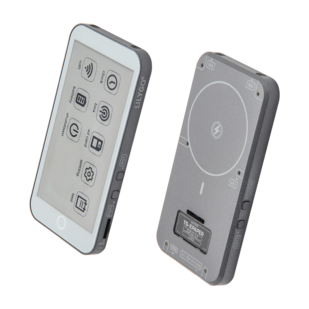
Preview
Physical Image
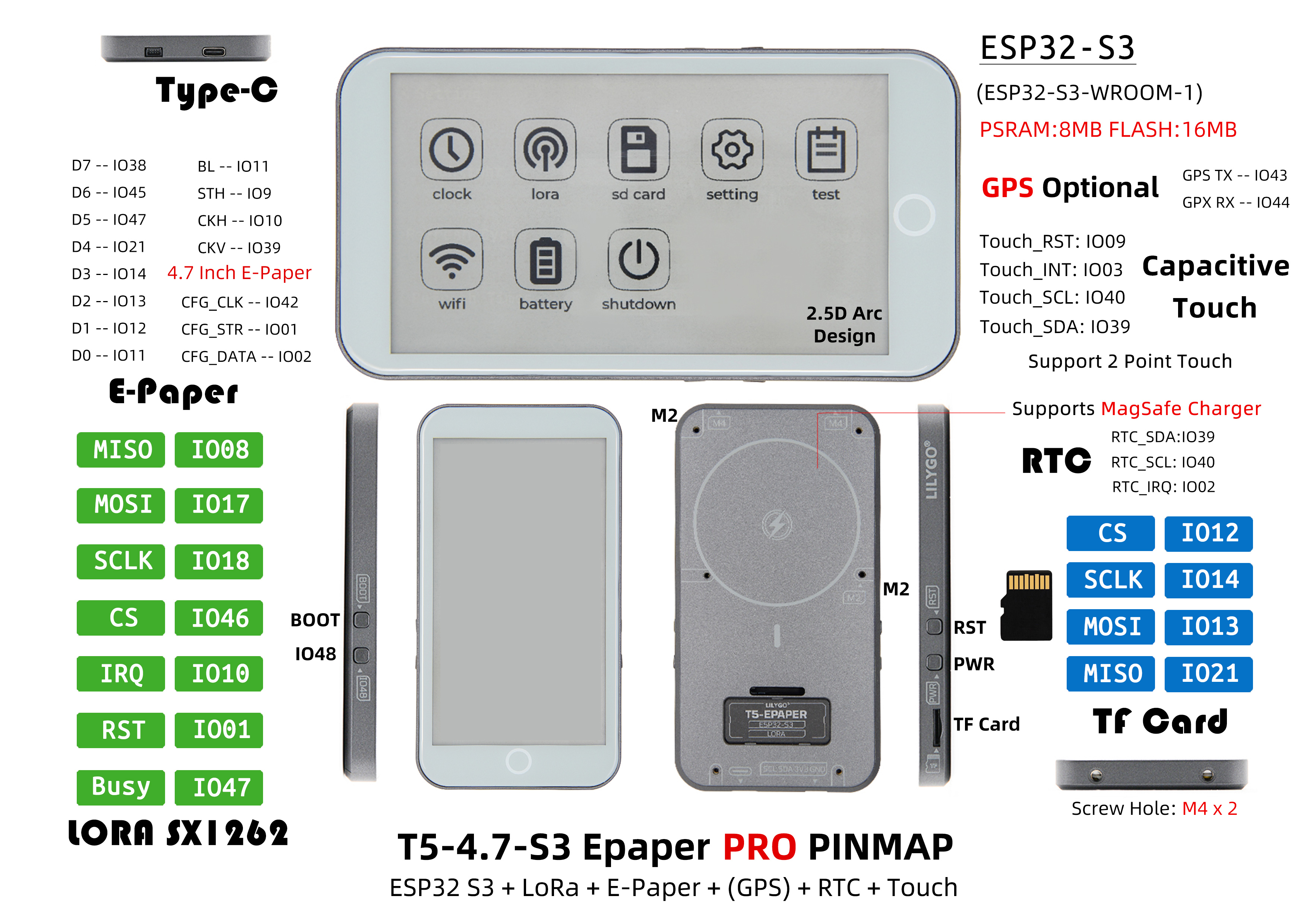
Pinout Diagram
Modules
MCU
- Chip: ESP32-S3-WROOM-1
- PSRAM: 8MB
- FLASH: 16MB
- Wireless: Wi-Fi 802.11 b/g/n; Bluetooth 5.0 (BLE)
- Other Notes: For more information, please visit Espressif Official ESP32-S3 Datasheet
E-Ink Display
- Driver IC: ED047TC1
- Size: 4.7-inch
- Resolution: 960×540 pixels
- Grayscale: 16-level grayscale
- Power Driver: TPS65185
Communication Modules
- LoRa: SX1262 chip, supports 433MHz~915MHz bands (selectable)
- GPS: MIA-M10Q GNSS module
- Wireless: 2.4GHz Wi-Fi & Bluetooth 5.0 (BLE)
Touchscreen
- Chip: GT911
- Type: Capacitive Touchscreen
- Support: Two-point touch
- Address: 0x5D
Power Management
- Battery: 3.7V 1500mAh Lithium Polymer Battery
- Charging Chip: BQ25896 (0x6B), BQ27220 (0x55)
- Charging Methods: MagSafe magnetic charging + USB charging
- E-Ink Display Power Driver: TPS65185 (0x68)
Peripherals & Expansion
- Real-Time Clock: PCF85063 (0x51)
- IO Expansion: PCA9535PW (0x20)
- Storage: TF Card Expansion
- Expansion Interfaces: 2 × QWIIC Interfaces
Overview
| Component | Description |
|---|---|
| MCU | ESP32-S3-WROOM-1 |
| FLASH | 16MB |
| PSRAM | 8MB |
| LoRa | SX1262 (433MHz~915MHz selectable) |
| GPS | MIA-M10Q GNSS Module |
| Display | ED047TC1 4.7-inch E-Ink Display (960×540, 16-level grayscale) |
| Touch | GT911 Capacitive Touchscreen (Two-point touch) |
| Power Driver | TPS65185 E-Ink Display Power Management |
| Battery Management | BQ25896, BQ27220 Charging Chips |
| Battery | 3.7V 1500mAh Lithium Polymer Battery |
| Charging Methods | MagSafe Magnetic Charging + USB Charging |
| Clock | PCF85063 Real-Time Clock |
| IO Expansion | PCA9535PW IO Expansion Chip |
| Storage | TF Card Expansion |
| Wireless | 2.4 GHz Wi-Fi & Bluetooth 5 (LE) |
| USB | Type-C Interface |
| Expansion Interfaces | 2 × QWIIC Interfaces |
| Buttons | 1 x RST Button + 1 x BOOT Button + 1 x IO48 Button + 1 x PWR Button |
| Mounting Holes | 2 × M4mm Screw Holes |
| Dimensions | 129×69×11mm |
Quick Start
Example Support
 -✅ bq25896:bq25896 test
 -✅ bq27220:bq27220 test
 -✅ display_test:Ink screen display test.
 -✅ factory:Factory firmware program.
 -✅ GPS:The GPS test needs to be done outdoors.
 -✅ io_extend:IO expansion chip test.
 -✅ lora_recv:SX1262 LoRa send test.
 -✅ lora_send:SX1262 LoRa recv test.
 -✅ lvgl_test:Test using LVGL as image engine.
 -✅ rtc_pcf8563:Real-time clock chip test.
 -✅ sd_card:SD card read test.
 -✅ touch:GT911 test.
PlatformIO
- Install Visual Studio Code, choose the installation according to your system type.
- Open the "Extensions" in the Visual Studio Code sidebar (or use Ctrl+Shift+X to open extensions), search for the "PlatformIO IDE" extension and download it.
- During the extension installation, you can go to GitHub to download the code. You can download the main branch code by clicking the green "<> Code" button, or download the "Releases" version from the sidebar.
- After the extension installation is complete, open the sidebar's Explorer (or use Ctrl+Shift+E to open it), click "Open Folder", find the recently downloaded project code folder (the entire folder), and click "Add". Now the project files are added to your workspace.
- Open the "platformio.ini" file in the project folder (PlatformIO will automatically open the "platformio.ini" for the corresponding folder), under the "[platformio]" section, uncomment to select the example program you want to flash (headed by "default_envs = xxx"), then click the "√" at the bottom left to compile. If the compilation is successful, connect the microcontroller to your computer, and click the "→" at the bottom left to flash.
Arduino
- Install Arduino IDE, choose the installation according to your system type.
- Open the "example" directory in the project folder, select the example project folder, and open the file ending with ".ino" to open the Arduino IDE project workspace.
- Open the "Tools" menu in the top right corner -> Select "Board" -> "Board Manager", find or search for "esp32", and download the board files by "Espressif Systems". Then return to the "Board" menu and select the board type under "ESP32 Arduino".
- Open the menu "File" -> "Preferences", find the "Sketchbook location" field, and copy all library files along with their folders from the "libraries" folder in the project directory to the "libraries" folder in this location.
- Select the correct settings in the "Tools" menu as shown in the table below.
ESP32-S3
| Setting | Value |
|---|---|
| Board | ESP32S3 Dev Module |
| Upload Speed | 921600 |
| USB Mode | Hardware CDC and JTAG |
| USB CDC On Boot | Enabled |
| USB Firmware MSC On Boot | Disabled |
| USB DFU On Boot | Disabled |
| CPU Frequency | 240MHz (WiFi) |
| Flash Mode | QIO 80MHz |
| Flash Size | 16MB (128Mb) |
| Core Debug Level | None |
| Partition Scheme | 16M Flash (3MB APP/9.9MB FATFS) |
| PSRAM | OPI PSRAM |
| Arduino Runs On | Core 1 |
| Events Run On | Core 1 |
- Select the correct port.
- Click the "√" in the top right corner to compile. If the compilation is successful, connect the microcontroller to your computer, and click the "→" in the top right corner to flash.
Development Platforms
Pin Overview
// BOARD PIN DEFINE
#define BOARD_GPS_RXD       44
#define BOARD_GPS_TXD       43
#define SerialMon           Serial
#define SerialGPS           Serial2

#define BOARD_I2C_PORT      (0)
#define BOARD_SCL           (40)
#define BOARD_SDA           (39)

#define BOARD_SPI_MISO      (21)
#define BOARD_SPI_MOSI      (13)
#define BOARD_SPI_SCLK      (14)

#define BOARD_TOUCH_SCL     (BOARD_SCL)
#define BOARD_TOUCH_SDA     (BOARD_SDA)
#define BOARD_TOUCH_INT     (3)
#define BOARD_TOUCH_RST     (9)

#define BOARD_RTC_SCL       (BOARD_SCL)
#define BOARD_RTC_SDA       (BOARD_SDA)
#define BOARD_RTC_IRQ       (2)

#define BOARD_SD_MISO       (BOARD_SPI_MISO)
#define BOARD_SD_MOSI       (BOARD_SPI_MOSI)
#define BOARD_SD_SCLK       (BOARD_SPI_SCLK)
#define BOARD_SD_CS         (12)

#define BOARD_LORA_MISO     (BOARD_SPI_MISO)
#define BOARD_LORA_MOSI     (BOARD_SPI_MOSI)
#define BOARD_LORA_SCLK     (BOARD_SPI_SCLK)
#define BOARD_LORA_CS       (46)
#define BOARD_LORA_IRQ      (10)
#define BOARD_LORA_RST      (1)
#define BOARD_LORA_BUSY     (47)

#define BOARD_BL_EN         (11)
#define BOARD_PCA9535_INT   (38)
#define BOARD_BOOT_BTN      (0)

// ED047TC1 --- e-ink paper
#define EP_SCL             (40)
#define EP_SDA             (39)
#define EP_INTR            (38)
#define EP_I2C_PORT      I2C_NUM_0

#define EP_D7              (8)
#define EP_D6              (18)
#define EP_D5              (17)
#define EP_D4              (16)
#define EP_D3              (15)
#define EP_D2              (7)
#define EP_D1              (6)
#define EP_D0              (5)
#define EP_CKV             (48) /* Control Lines */
#define EP_STH             (41)
#define EP_LEH             (42)
#define EP_STV             (45)
#define EP_CKH             (4)   /* Edges */

// PCA9535
// Extend the interface and set the read/write ports via I2C.
// IO1X
#define PCA9535_IO10_EP_OE          // EP Output enable source driver
#define PCA9535_IO11_EP_MODE        // EP Output mode selection gate driver
#define PCA9535_IO12_BUTTON
#define PCA9535_IO13_TPS_PWRUP
#define PCA9535_IO14_VCOM_CTRL
#define PCA9535_IO15_TPS_WAKEUP
#define PCA9535_IO16_TPS_PWR_GOOD
#define PCA9535_IO17_TPS_INT
// IO0X
#define PCA9535_IO00
#define PCA9535_IO01
#define PCA9535_IO02
#define PCA9535_IO03
#define PCA9535_IO04
#define PCA9535_IO05
#define PCA9535_IO06
#define PCA9535_IO07
Related Tests
Test data to be supplemented
FAQ
Q. What should I do if I still don't know how to set up the programming environment after reading the above tutorial?
A. If you still don't understand how to set up the environment after reading the above tutorial, you can refer to the LilyGo-Document documentation for setup instructions.Q. Why does Arduino IDE prompt me to upgrade library files when I open it? Should I upgrade or not?
A. Choose not to upgrade library files. Different versions of library files may not be compatible with each other, so upgrading is not recommended.Q. What's the difference between MagSafe charging and USB charging?
A. MagSafe provides convenient magnetic charging experience, while USB charging is the traditional wired charging method. Both can be used simultaneously.Q. Why does my board keep failing to flash?
A. Please hold the "BOOT" button and try downloading the program again.
Projects
Resources
- ESP32-S3 Datasheet
- ED047TC1 Screen Datasheet
- MIA-M10Q GPS Datasheet
- TPS65185 Power Driver
- CST226SE Touch Controller