


 English
LILYGO Sim Shield Expansion Board User Guide
Version History:
| Version | Update date | Update description |
|---|---|---|
| T-SimShield-Rev1.0 | 2024-08-10 | Initial release, supports all Sim series mainboards |
| T-SimShield-Rev1.1 | 2024-11-05 | Optimized power circuit for enhanced stability |
Purchase Links
| Product | Features | Compatible Mainboards | Link |
|---|---|---|---|
| Sim Shield | Triple-Channel Current Sensing, LoRa Transceiver, RS485, Wide Voltage Input | All LilyGo T-Sim Series Mainboards | LILYGO Mall |
Table of Contents
- Overview
- Electrical Parameters
- Mainboard Compatibility Configuration
- Interface Description
- Usage Examples
- Schematics & Resources
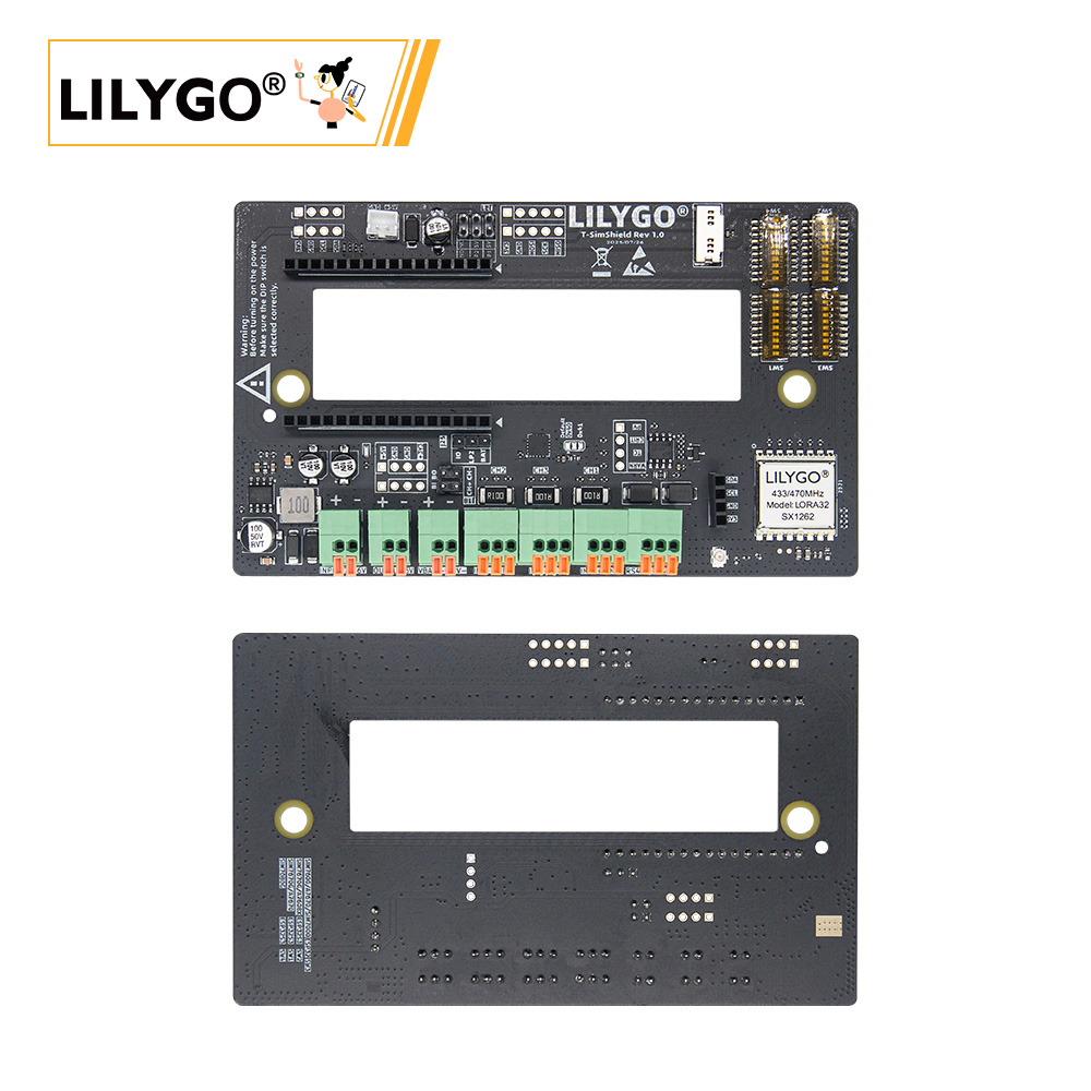
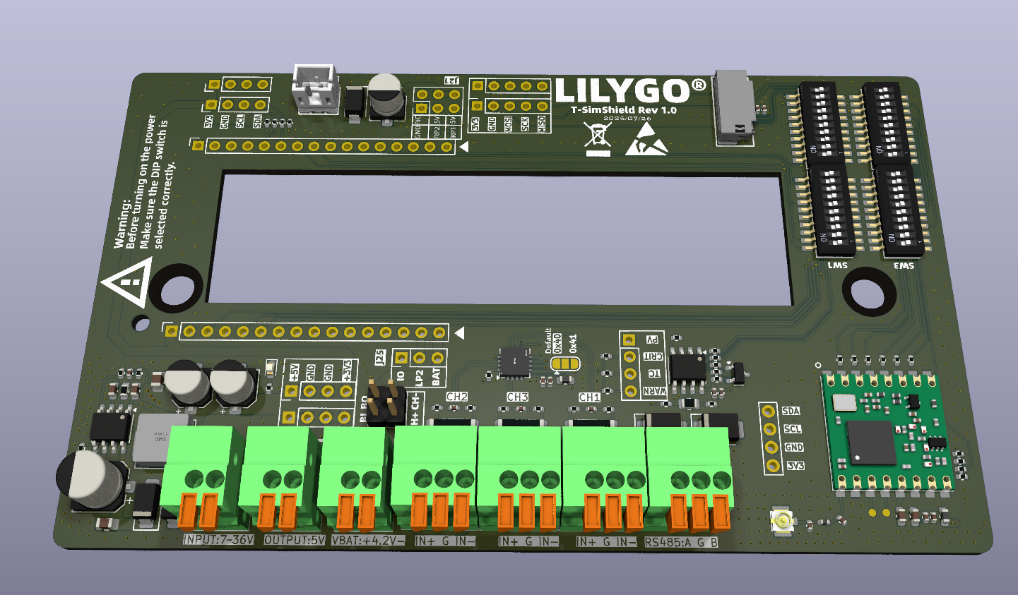
Overview
The Sim Shield is a multifunction expansion board specifically designed for the LilyGo T-Sim Series, integrating the following features:
- Triple-Channel Current Sensing: Based on the INA3221 chip, supports independent current monitoring.
- LoRa Wireless Communication: Integrated SX1262 module, supports long-range transmission.
- Wide Voltage DC Input: Supports 7~36V DC input with built-in voltage regulation circuitry.
- RS485 Interface: Hardware auto direction control (ADCDC), supports industrial communication.
- I2C/SPI Expansion: Provides standard interfaces for connecting peripherals.
⚠️ Important Warning:
Always check jumper cap and DIP switch settings before powering on. Incorrect configuration may cause hardware damage.
Electrical Parameters
| Feature | Parameter |
|---|---|
| DC Input Voltage | 7~36V |
| Battery Input Voltage | 4.2V (max) |
| Charging Current | Provided by mainboard |
| +5V Output | Max 2A |
| +3.3V Output | Provided by mainboard (recommended load ≤100mA) |
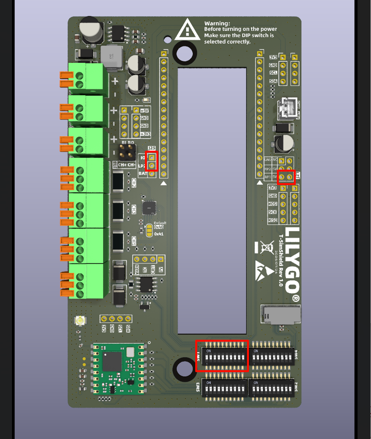
Mainboard Compatibility Configuration
1. SIM7000G / A7670X / A7608X (ESP32 Version)
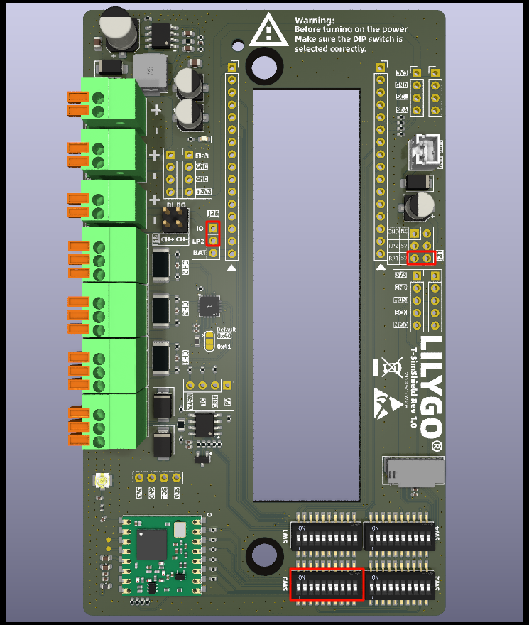
| Jumper/Switch | Setting | Description |
|---|---|---|
| J25 | IO → LP2 | Select logic level |
| J21 | RP1 → 5V | Select 5V power source |
| SW3 | ON | Enable this configuration |
| SW1/SW2/SW4 | OFF | Must be OFF |
Applicable Models:
Note: For A7670X/A7608X, a resistor needs to be removed to use the Sim Shield. See this link for details.
Pin Mapping:
| Signal | GPIO |
|---|---|
| SIMSHIELD_MOSI | 23 |
| SIMSHIELD_MISO | 19 |
| SIMSHIELD_SCK | 18 |
| SIMSHIELD_SD_CS | 32 |
| SIMSHIELD_RADIO_BUSY | 39 |
| SIMSHIELD_RADIO_CS | 5 |
| SIMSHIELD_RADIO_IRQ | 34 |
| SIMSHIELD_RADIO_RST | 15 |
| SIMSHIELD_RS_RX | 13 |
| SIMSHIELD_RS_TX | 14 |
| SIMSHIELD_SDA | 21 |
| SIMSHIELD_SCL | 22 |
2. SIM7600X (ESP32 Version)
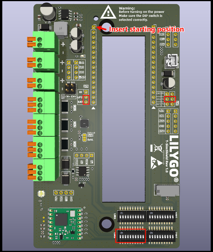
| Jumper/Switch | Setting | Description |
|---|---|---|
| J25 | IO → BAT | Select battery power |
| J21 | RP2 → 5V | Select 5V power source |
| SW3 | ON | Enable this configuration |
| SW1/SW2/SW4 | OFF | Must be OFF |
Applicable Models:
Pin Mapping (Special Notes):
| Signal | GPIO | Multiplexed Function |
|---|---|---|
| SIMSHIELD_SD_CS | 32 | SIM7600 DTR pin |
| SIMSHIELD_RADIO_IRQ | 34 | SIM7600 STATUS pin |
| SIMSHIELD_RS_RX | 12 | SIM7600 LED pin |
Note: These three GPIOs are occupied by the Sim Shield. Do not use them for other purposes.
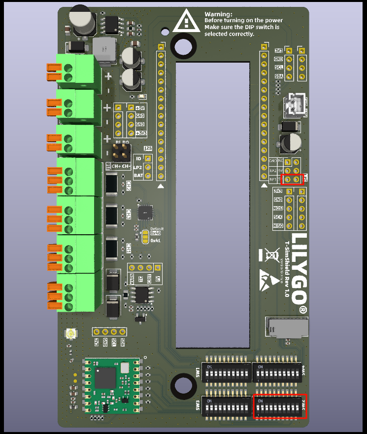
3. SIM7670G (ESP32-S3 Version)

| Jumper/Switch | Setting | Description |
|---|---|---|
| J25 | IO → LP2 | Select logic level |
| J21 | RP1 → 5V | Select 5V power source |
| SW2 | ON | Enable this configuration |
| SW1/SW3/SW4 | OFF | Must be OFF |
Applicable Models:
Pin Mapping:
| Signal | GPIO |
|---|---|
| SIMSHIELD_MOSI | 15 |
| SIMSHIELD_MISO | 7 |
| SIMSHIELD_SCK | 16 |
| SIMSHIELD_SD_CS | 46 |
| SIMSHIELD_RADIO_BUSY | 38 |
| SIMSHIELD_RADIO_CS | 39 |
| SIMSHIELD_RADIO_IRQ | 6 |
| SIMSHIELD_RADIO_RST | 40 |
| SIMSHIELD_RS_RX | 41 |
| SIMSHIELD_RS_TX | 42 |
| SIMSHIELD_SDA | 2 |
| SIMSHIELD_SCL | 1 |
4. A7608X (ESP32-S3 Version)
| Jumper/Switch | Setting | Description |
|---|---|---|
| J25 | IO → LP2 | Select logic level |
| J21 | Not Connected | - |
| SW2 | ON | Enable this configuration |
| SW1/SW3/SW4 | OFF | Must be OFF |
Applicable Models:
Pin Mapping:
| Signal | GPIO |
|---|---|
| SIMSHIELD_MOSI | 11 |
| SIMSHIELD_MISO | 10 |
| SIMSHIELD_SCK | 12 |
| SIMSHIELD_SD_CS | 45 |
| SIMSHIELD_RADIO_BUSY | 38 |
| SIMSHIELD_RADIO_CS | 39 |
| SIMSHIELD_RADIO_IRQ | 9 |
| SIMSHIELD_RADIO_RST | 40 |
| SIMSHIELD_RS_RX | 41 |
| SIMSHIELD_RS_TX | 42 |
| SIMSHIELD_SDA | 2 |
| SIMSHIELD_SCL | 1 |
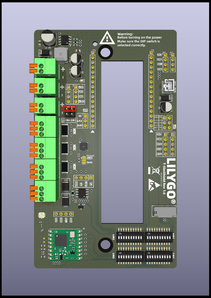
5. SIM7080G (ESP32-S3 PMU Version)

| Jumper/Switch | Setting | Description |
|---|---|---|
| J25 | Not Connected | - |
| J21 | Not Connected | - |
| SW4 | ON | Enable this configuration |
| SW1/SW2/SW3 | OFF | Must be OFF |
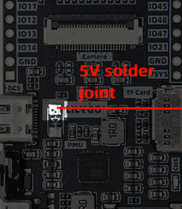
Important Notes:
- SIM7080G does not expose external battery pins. The 18650 battery holder positive terminal needs to be soldered to a designated position.
- The 18650 battery holder on the mainboard must be removed (conflicts with Sim Shield).
- The
DC5andVSYSpins must be left unconnected. - Additional wires need to be soldered to support 5V input (see diagram below).
Applicable Models:
Pin Mapping:
| Signal | GPIO |
|---|---|
| SIMSHIELD_MOSI | 11 |
| SIMSHIELD_MISO | 13 |
| SIMSHIELD_SCK | 12 |
| SIMSHIELD_SD_CS | 21 |
| SIMSHIELD_RADIO_BUSY | 48 |
| SIMSHIELD_RADIO_CS | 45 |
| SIMSHIELD_RADIO_IRQ | 8 |
| SIMSHIELD_RADIO_RST | 47 |
| SIMSHIELD_RS_RX | 2 |
| SIMSHIELD_RS_TX | 1 |
| SIMSHIELD_SDA | 44 |
| SIMSHIELD_SCL | 43 |
6. Standard Series (SIM7000G/A7670X/SIM7670G/SIM7080G)
| Jumper/Switch | Setting | Description |
|---|---|---|
| J25 | IO → LP2 | Select logic level |
| J21 | RP1 → 5V | Select 5V power source |
| SW1 | ON | Enable this configuration |
| SW2/SW3/SW4 | OFF | Must be OFF |
Pin Mapping (General):
| Signal | GPIO |
|---|---|
| SIMSHIELD_MOSI | 11 |
| SIMSHIELD_MISO | 13 |
| SIMSHIELD_SCK | 12 |
| SIMSHIELD_SD_CS | 37 |
| SIMSHIELD_RADIO_BUSY | 15 |
| SIMSHIELD_RADIO_CS | 38 |
| SIMSHIELD_RADIO_IRQ | 14 |
| SIMSHIELD_RADIO_RST | 39 |
| SIMSHIELD_RS_RX | 40 |
| SIMSHIELD_RS_TX | 41 |
| SIMSHIELD_SDA | 3 |
| SIMSHIELD_SCL | 2 |
Interface Description
1. Battery Connection
- Connect the external battery interface to the mainboard battery interface via a jumper cap.
- Note: If using an external battery, do NOT install a battery in the mainboard's 18650 socket.
2. Current Monitoring Setup
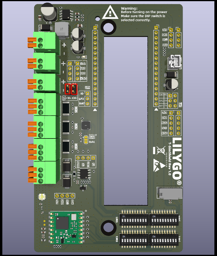
- Vertical Jumper Cap: Routes battery current to INA3221 Channel 2, enabling charge/discharge current monitoring.
- No Jumper Cap: Monitors the screw terminal interface current.
- Note: When using battery monitoring, do NOT connect the screw terminals.
3. 5V Power Interface
- 2.00mm 2Pin JST interface for external power supply.
- Can also be connected directly to the mainboard solar port for charging (requires disconnecting J21 jumper).
- This interface is recommended for primary power due to lower voltage drop.
4. SD Card Interface
- The Sim Shield remaps the SPI interface.
- After using the Sim Shield, the SD card must be inserted into the expansion board, NOT the mainboard.
5. RS485 Interface
- Hardware auto direction control (ADCDC).
- Recommended communication baud rate ≤115200.
6. I2C Interface
- Supports standard 0.96-inch OLED displays.
- Note on Pin Order: Ensure the OLED interface pinout is correct.
7. SPI Interface
- Exposes the SPI bus for the SD card and LoRa module.
8. Current Sensing Channels
| Channel | Availability | Description |
|---|---|---|
| CH1 | Conditionally Available | Unavailable if battery is connected via jumper |
| CH2 | Conditionally Available | Unavailable if selected for battery monitoring (screw terminals unavailable) |
| CH3 | Always Available | Free to use |
Terminal Definitions:
- IN+: Current flow direction into the sensor.
- G: Load GND.
- IN-: Current flow direction out of the sensor.
Usage Examples
| Example | Description | Link |
|---|---|---|
| SimShield_LoRaWAN | LoRaWAN Communication Example | View |
| SimShield_LoRaReceive | LoRa Receive Example | View |
| SimShield_LoRaTransmit | LoRa Transmit Example | View |
| SimShieldCurrentSensor | Current Sensor Example | View |
| SimShieldFactory | Factory Test Program | View |
| SerialRS485 | RS485 Communication Example | View |
Schematics & Resources
- Schematic: T-SimShield-Rev1.0.pdf
- Solar Panel Specifications: 3D5ETR00372_233153V01_20250828.pdf
- Compatibility List: Supports all LilyGo T-Sim series mainboards.
Summary of Important Notes
- Always check jumper and DIP switch settings before powering on.
- Do NOT install a battery in the mainboard's 18650 socket when using an external battery.
- The SD card must be inserted into the expansion board, NOT the mainboard.
- Pin mappings differ between mainboard models. Configure according to the corresponding table.
- Recommended RS485 baud rate is ≤115200.