


 English
LILYGO T-TWR
Note: T-TWR has UHF and VHF receiver versions. The main difference is the walkie-talkie frequency band. UHF walkie-talkie frequency band is 400-480MHz, VHF walkie-talkie frequency band is 134-174MHz.
Version History:
| Version | Update date | Update description |
|---|---|---|
| T-TWR REV2.1 | Current Version |
Purchase Links
| Product | SOC | FLASH | PSRAM | Link |
|---|---|---|---|---|
| T-TWR REV2.1 | ESP32-S3-WROOM-1-N16R8 | 16MB | 8MB (Octal SPI) | LILYGO Mall |
Table of Contents
Description
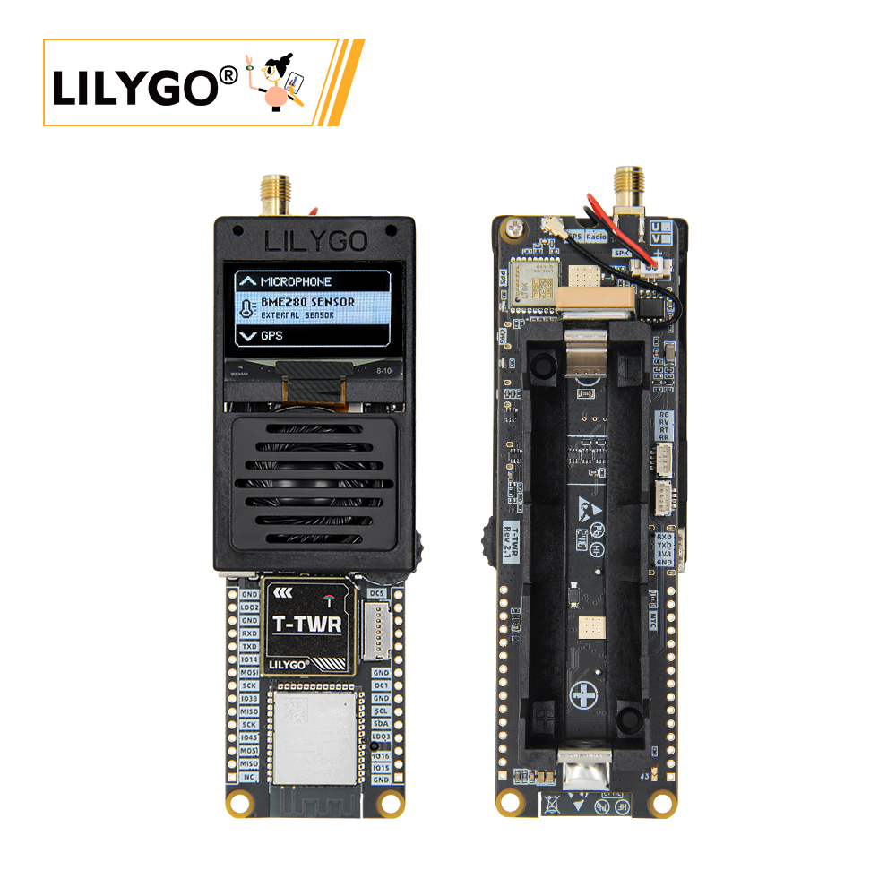
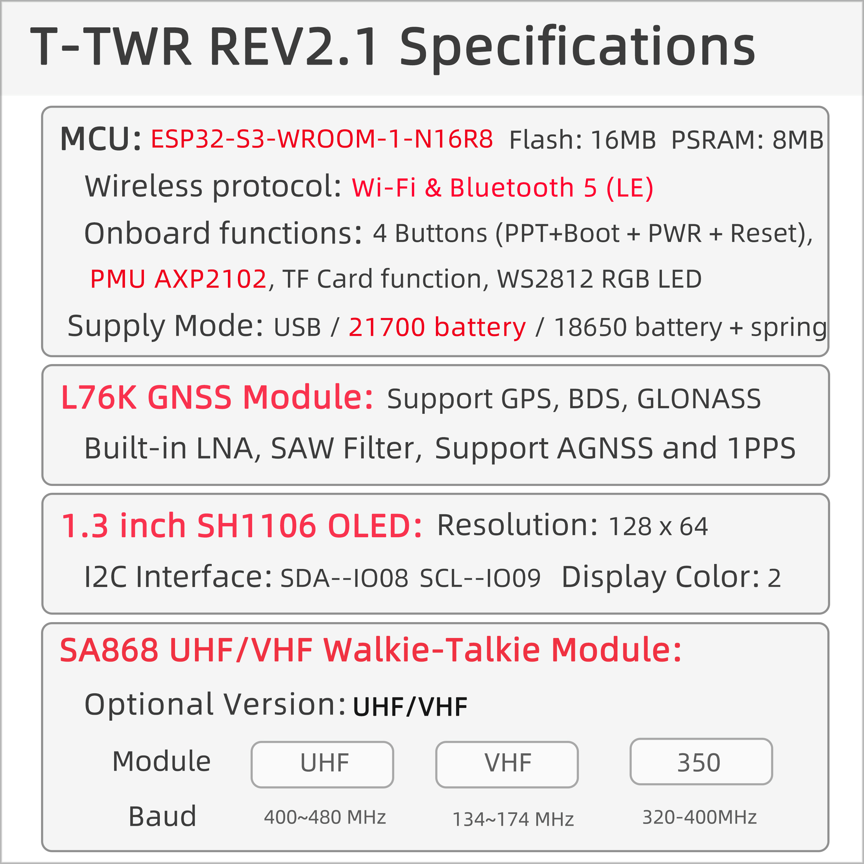
LILYGO T-TWR REV2.1 is a highly integrated development board based on ESP32-S3-WROOM-1-N16R8, equipped with 16MB Flash and 8MB PSRAM, supporting Wi-Fi/Bluetooth 5 (LE) dual-mode communication, built-in PMU AXP2102 power management unit, supporting USB/21700/18650 battery multiple power supply modes, suitable for portable device development.
Core Features
- Multi-system Positioning: L76K GNSS module supports GPS, BDS, GLONASS multi-system positioning and AGNSS assistance
- Walkie-Talkie Function: SA868 UHF/VHF walkie-talkie module, optional 134-174MHz or 350-480MHz frequency bands
- HD Display: 1.3-inch SH1106 OLED screen (128×64 resolution, I²C interface)
- Power Management: AXP2102 power management chip, supports multiple power supply modes
- Rich Interfaces: TF card expansion, microphone input, environmental sensor interface, RGB status indicator
- Portable Design: Supports 21700/18650 batteries, suitable for outdoor applications
Preview
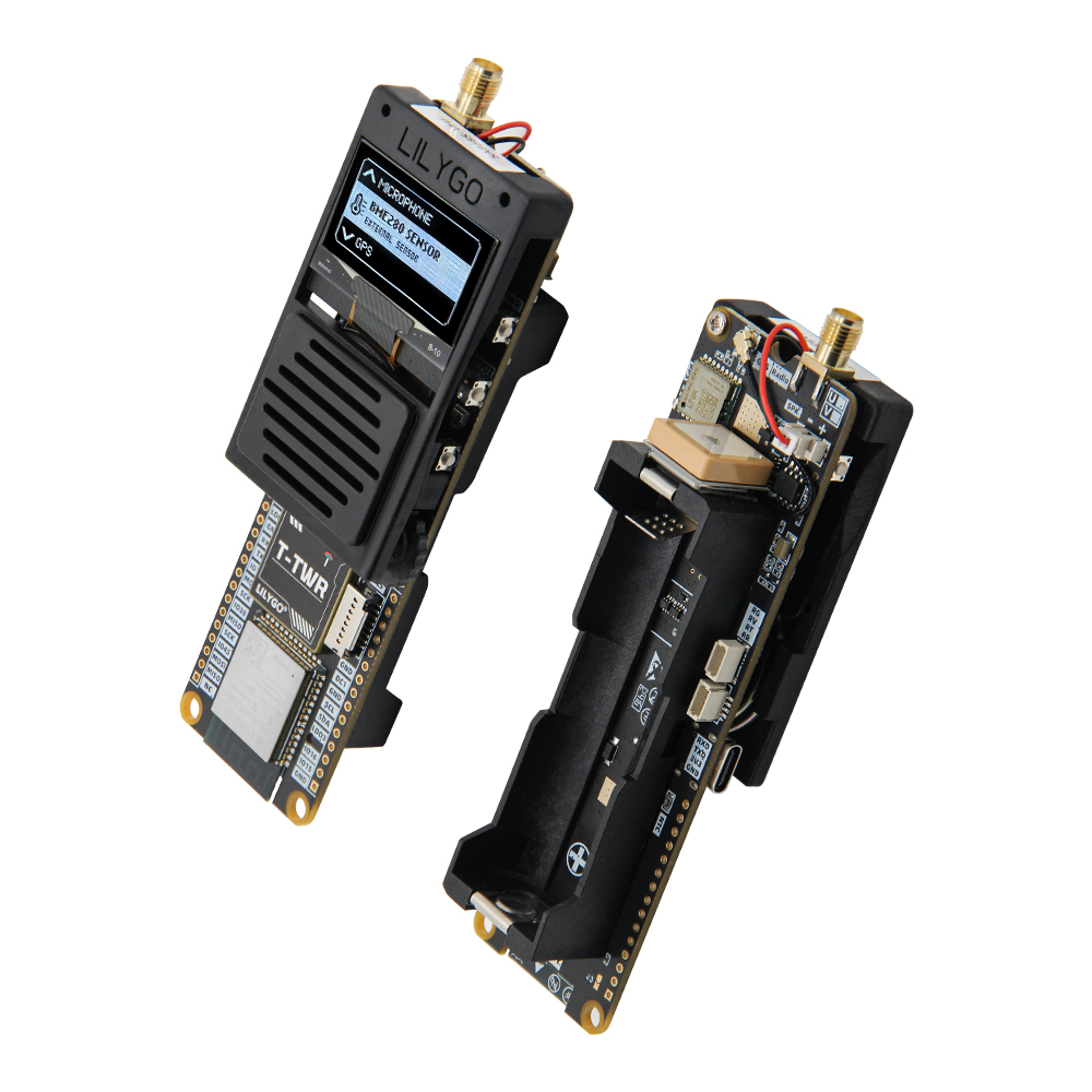
Physical Image
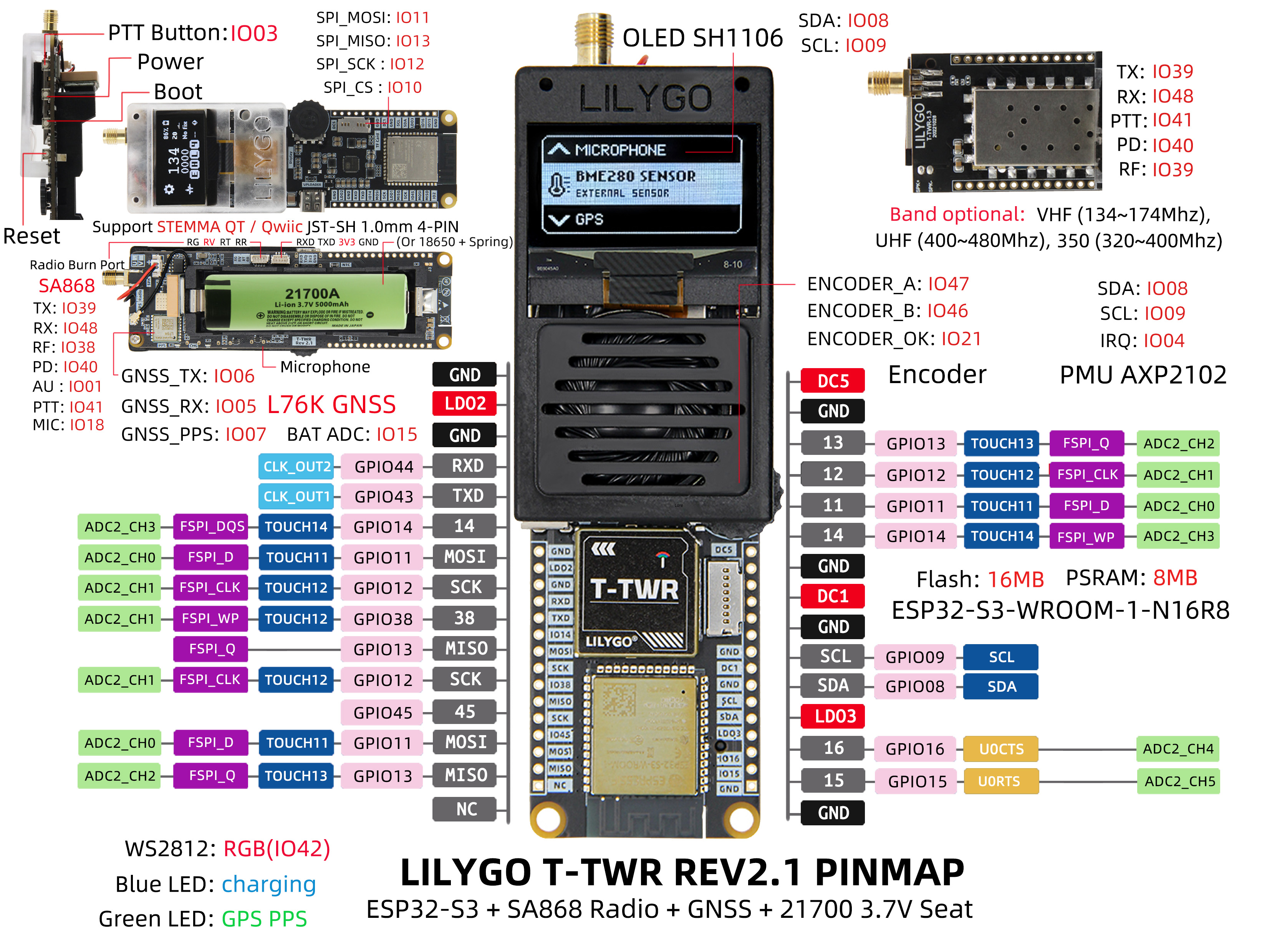
Pin Diagram
Modules
MCU
- Chip: ESP32-S3-WROOM-1-N16R8
- PSRAM: 8M (Octal SPI)
- FLASH: 16M
- Wireless: Wi-Fi 802.11 b/g/n; Bluetooth 5.0 (LE)
- Additional Information: More information available at Espressif Official ESP32-S3 Datasheet
Display Module
- Screen: 1.3-inch SH1106 OLED
- Resolution: 128×64 pixels
- Interface: I²C (SDA-1008/SCL-1009)
- Compatible Library: U8g2
Positioning Module
- Chip: L76K GNSS
- Supported Systems: GPS, BDS, GLONASS
- Assisted Positioning: AGNSS
- Compatible Library: TinyGPSPlus
Communication Module
- Chip: SA868
- Frequency Band Options:
- UHF Version: 400-480MHz
- VHF Version: 134-174MHz
- Function: Walkie-talkie communication
Power Management
- Chip: AXP2102 PMU
- Power Supply Methods: USB, 21700 battery, 18650 battery
- Battery Type: Supports 21700/18650 batteries + spring battery holder
Audio Module
- Chip: RS2257XC6
- Function: Audio collection and processing
Overview
| Component | Description |
|---|---|
| MCU | ESP32-S3-WROOM-1-N16R8 |
| FLASH | 16MB |
| PSRAM | 8MB (Octal SPI) |
| Display | 1.3-inch SH1106 OLED (128×64) |
| Walkie-Talkie | SA868 UHF/VHF Module |
| Audio | RS2257XC6 Audio Collection Module |
| GNSS | L76K GNSS Module (GPS/BDS/GLONASS) |
| Power Management | AXP2102 PMU |
| Battery | 21700 Battery / 18650 Battery |
| LED | WS2812 RGB Status Indicator |
| Encoder | Supports rotary encoder control |
| Storage | TF Card Expansion Interface |
| Wireless | 2.4GHz Wi-Fi + Bluetooth 5.0 (LE) |
| USB | 1 × USB Port and OTG (TYPE-C) |
| IO Interface | 2 × 15pin Expansion IO Interface |
| Expansion Interface | 2 × 1mm 4-pin STEMMA QT/QWIIC Interface + Antenna Interface |
| Buttons | 1 x RESET + 1 x BOOT + 1 x PWR + 1 x PTT |
| Power | 5V/500mA |
| Mounting Holes | 2 × 2mm Positioning Holes |
| Dimensions | Product: 126×39×29mm Antenna: 200mm |
Quick Start
Example Support
examples/
├── Factory                         # TWR Factory Application
├── GPS_Basic_Example               # GPS example
├── GPS_Full_Example                # GPS example
├── Pixels_RGBWstrandtest           # Pixels example
├── Pixels_Strandtest_Example       # Pixels example
├── SA868_ATDebug_Example           # Radio  AT Debug example
├── SA868_ESPSendAudio_Example      # Radio frequency sends ESP32 signal
├── SD_Test_Example                 # SD Test Example
├── SD_Time_Example                 # SD Time Example
├── WAV_Player                      # WAV Player
├── TFT_ArcFill_Example             # Screen extension example
├── TFT_Keypad_240x320_Example      # Screen extension example
├── U8g2_FontUsage_Example          # Onboard OLED U8G2 example
├── U8g2_GraphicsTest_Example       # Onboard OLED U8G2 example
└── U8g2_UpdateArea_Example         # Onboard OLED U8G2 example
PlatformIO
- Install Visual Studio Code and Python
- Search for the
PlatformIOplugin in theVisualStudioCodeextension and install it. - After the installation is complete, you need to restart
VisualStudioCode - After restarting
VisualStudioCode, selectFilein the upper left corner ofVisualStudioCode->Open Folder-> select theT-TWRdirectory - Click on the
platformio.inifile, and in theplatformiocolumn, cancel the sample line that needs to be used, please make sure that only one line is valid - Click the (✔) symbol in the lower left corner to compile
- Connect the board to the computer USB
- Click (→) to upload firmware
- Click (plug symbol) to monitor serial output
Arduino
- Install Arduino IDE
- Install Arduino ESP32
- Copy all the folders in the
T-TWR/libdirectory to<C:\Users\UserName\Documents\Arduino\libraries>. If there is nolibrariesdirectory, please create a new one. Please note that you are not copying thelibdirectory, but copying the folders in the lib directory - Open ArduinoIDE ->
Tools
| Arduino IDE Setting | Value |
| ------------------------------------ | --------------------------------- |
| Board | ESP32S3 Dev Module |
| Port | Your port |
| USB CDC On Boot | Enable |
| CPU Frequency | 240MHZ(WiFi) |
| Core Debug Level | None |
| USB DFU On Boot | Disable |
| Erase All Flash Before Sketch Upload | Disable |
| Events Run On | Core1 |
| Flash Mode | QIO 80MHZ |
| Flash Size | 16MB(128Mb) |
| Arduino Runs On | Core1 |
| USB Firmware MSC On Boot | Disable |
| Partition Scheme | 16M Flash(3M APP/9.9MB FATFS) |
| PSRAM | OPI PSRAM |
| Upload Mode | UART0/Hardware CDC |
| Upload Speed | 921600 |
| USB Mode | CDC and JTAG |- The options in bold are required, others are selected according to actual conditions.
- Insert USB into the PC and click Upload <If the upload fails, View the FAQ below>
Development Platforms
Pin Overview
⚠⚠⚠ Precautions (special matters):
- The glue stick (RF) antenna must be connected. If the antenna is not connected, the RF module may be damaged, and the PMU will automatically turn off the power output
- A separate USB power supply may not meet the power supply requirements, please connect the battery to use , The Rev2.1 version must use a battery to power the radio frequency unit and cannot use USB to work alone (because the RF current is very large and the noise can be minimized using battery power)
- Please note that when adjusting to high power transmission, please ensure that the battery has sufficient discharge capacity, otherwise the PMU will automatically shut down due to insufficient current.
- TWR Rev2.0 has two versions, one comes with NiceRF AT firmware, and the other is a community version without any functions. For the community version, please jump to OpenRTX to burn OpenRTX SA8x8 firmware for use. For novices, it is recommended to use NiceRF firmware.
- TWR Rev2.1 is version agnostic. The built-in NiceRF firmware can be flashed to OpenRTX firmware, but the NiceRF firmware cannot be restored after flashing.
⚠ Unable to download the program, the error is shown below.
Click to view detailed steps
Flash: [==== ] 35.7% (used 467813 bytes from 1310720 bytes) Configuring upload protocol... AVAILABLE: cmsis-dap, esp-bridge, esp-builtin, esp-prog, espota, esptool, iot-bus-jtag, jlink, minimodule, olimex-arm-usb-ocd, olimex-arm-usb-ocd-h, olimex-arm-usb-tiny-h, olimex-jtag-tiny, tumpa CURRENT: upload_protocol = esptool Looking for upload port... Auto-detected: COM236 Uploading .pio\build\uhf_band\firmware.bin esptool.py v4.5 Serial port COM236 Connecting... A serial exception error occurred: ClearCommError failed (PermissionError(13, 'The device does not recognize the command.', None, 22)) Note: This error originates from pySerial. It is likely not a problem with esptool, but with the hardware connection or drivers. For troubleshooting steps visit: https://docs.espressif.com/projects/esptool/en/latest/troubleshooting.html *** [upload] Error 1 ================================================================================================================ [FAILED] Took 8.75 seconds ================================================================================================================- Step
- Press the PWR button for one second to make sure the TWR is powered on
- Press and hold the BOOT button (without releasing it), then press the RST button, then release the RST button, and finally release the BOOT button
- Click the upload button in the IDE and wait for the upload to complete
- Press the RST button to exit the download mode
⚠ Can I change the voltage of the peripheral?
Click to view detailed steps
1. Not recommended, changing the peripheral voltage may cause abnormal operation, please do not change the default voltage setting of the peripheral, please refer to the voltage setting in the sample program.⚠ Why can't I test the charging current to reach the set current?
Click to view detailed steps
1. If you use a USBC cable with low quality or too large or too long wire resistance, there will be a large internal resistance, and there is no rated 5V input on the board, so the PMU will think that the power supply voltage is insufficient, so the rated charging current cannot be reached. ,The solution is to replace the high-quality USBC wire, reduce the length of the wire to meet the requirements of the PMU input voltage
2. You can measure the voltage at both ends of the figure below to see if it can meet the 5V input voltage required by the PMU

- Please note that if the charging current is set to 1A, please install a suitable heat sink above the PMU to reduce the risk of heat and damage caused by overheating.
⚠ When you think there is a problem with the board, you can try to burn our factory firmware for testing, you can first rule out whether it is a hardware problem
⚠ I don’t have a 21700 battery, can I replace the battery holder with a 18650** battery holder?**
Click to view detailed steps
1. The board is compatible with 21700 and 18650 battery holders, if you have the ability to replace it, please note that **LilyGo does not bear the risk of replacing the battery holder without authorization, damage and Brought to work abnormally**⚠ Can't turn on automatically after connecting the battery?
Click to view detailed steps
1. Connect the battery separately, you need to press the **PWR button** for one second, the board will start the action, press and hold the **PWR** button for 6 seconds to shut down, the shutdown time can be set by software , In the latest version (Rev2.1), inserting the battery will automatically power on.TWR currently has two modes before leaving the factory, one is flashed with regular firmware and uses the esp built-in boot, and the other uses TinyUF2 as the boot program. For novices, please see here
How to enter TinyUF2 boot mode?

Click to view detailed steps
1. Before entering TinyUF2, the boot program must have been flashed. If it has not been written, please [see here](https://github.com/Xinyuan-LilyGO/T-TWR/blob/master/firmware/README.MD)
2. Press the RST button
3. After pressing the RST button for one second, press the BOOT button. The disk will be ejected on the computer.
4. At this time, drag the firmware with the suffix uf2 into the disk to upgrade the device.
⚠ There is a microphone port on the bottom of the board, do I need to install a microphone? Only for Rev2.0, Rev2.1 has removed the external microphone interface
Click to view detailed steps
1. No, there is already a condenser microphone on board. If you need to use a wired microphone, please remove the board microphone. Please note that **LilyGo will not be responsible for the damage and abnormality of the board caused by unauthorized disassembly of the microphone**