LILYGO T-Display S3 AMOLED 1.43
Version History:
| Version |
Update Date |
Update Description |
| T-Display-S3-AMOLED-1.43_V1.0 |
2024-05-20 |
Initial Version |
| T-Display-S3-AMOLED-1.43-1.75_V1.0 |
2024-11-25 |
Added FPC cable, added H0175Y003AM screen support |
| T-Display-S3-AMOLED-1.43-1.75_V1.0 |
2025-01-13 |
Added DO0143FMST10 screen support |
Purchase Link
| Product |
SOC |
FLASH |
PSRAM |
Link |
| T-Display-S3-AMOLED-1.43-1.75 |
ESP32S3R8 |
16M |
8M (Octal SPI) |
LILYGO Mall |
Table of Contents
Description
T-Display-S3-AMOLED-1.43-1.75 is an intelligent display development board integrating the high-performance ESP32-S3 Wi-Fi/Bluetooth dual-mode chip, specifically designed for IoT and interactive applications. At its core is a 1.43-inch AMOLED display providing 466×466 pixel high resolution, supporting touch operation and featuring a built-in PCF8563 real-time clock (RTC) for precise time management. Hardware configuration includes 16MB FLASH storage, 8MB Octal SPI PSRAM memory, supports Micro SD card expansion storage, while integrating battery level detection (ADC) function and Type-C power supply interface, convenient for mobile scenarios. The development board provides rich expansion interfaces (such as SPI, I2C, GPIO, etc.), compatible with touchscreen interaction and SD card data read/write, suitable for applications such as smart wearables, industrial control, embedded GUI development, combining high performance with low power consumption characteristics.
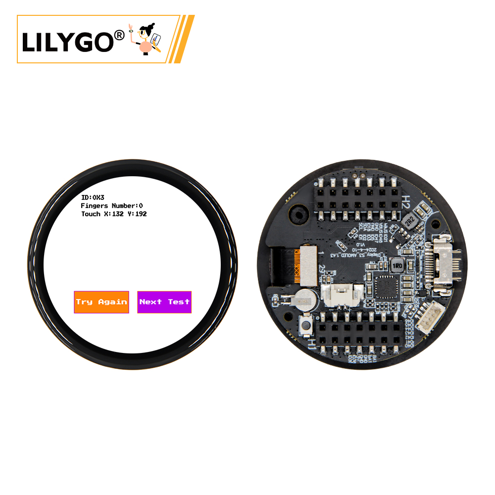
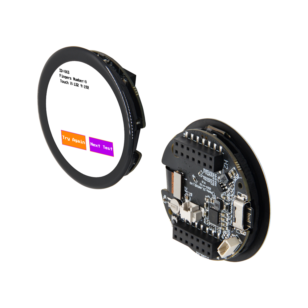
Preview
Physical Images
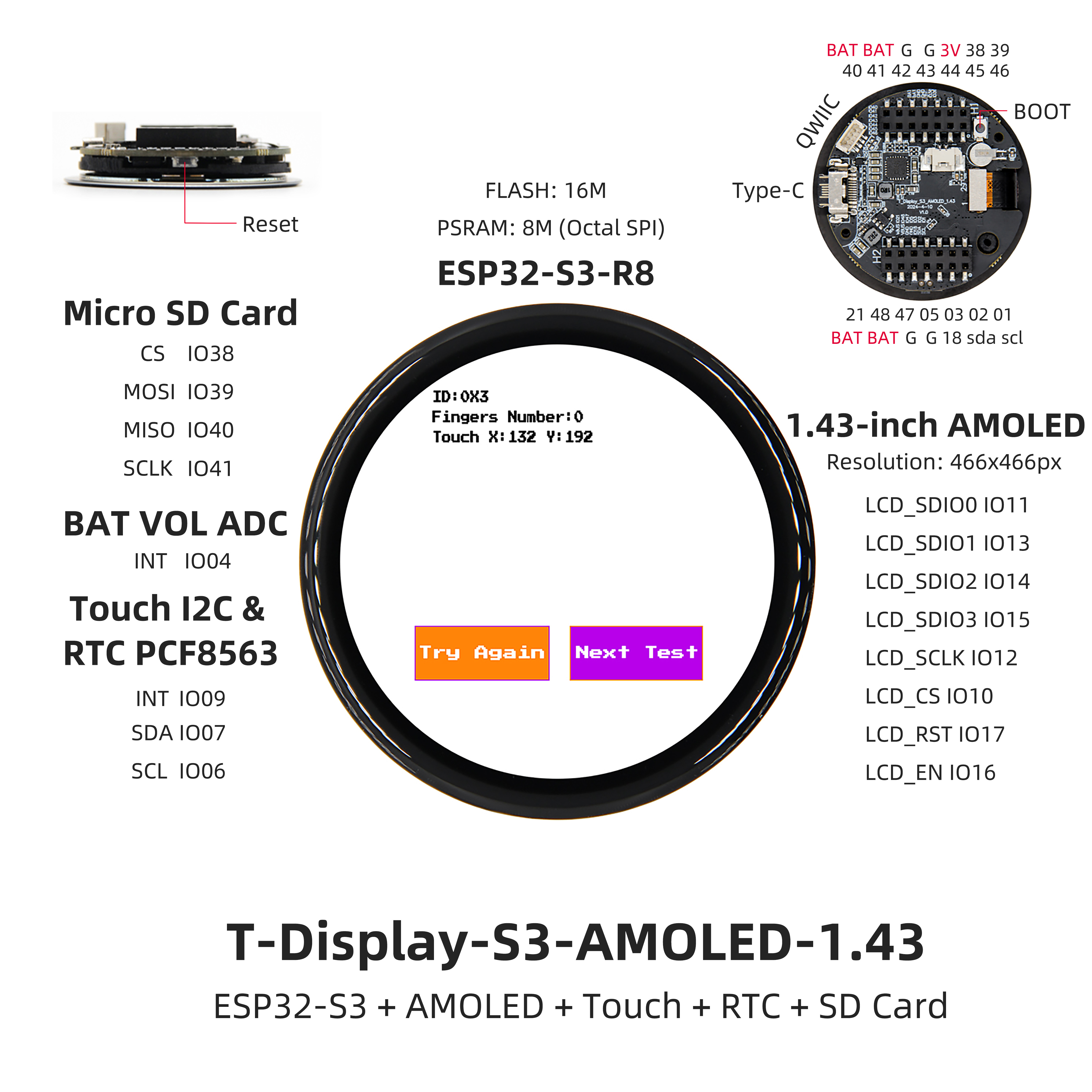
Pinout Diagram
Modules
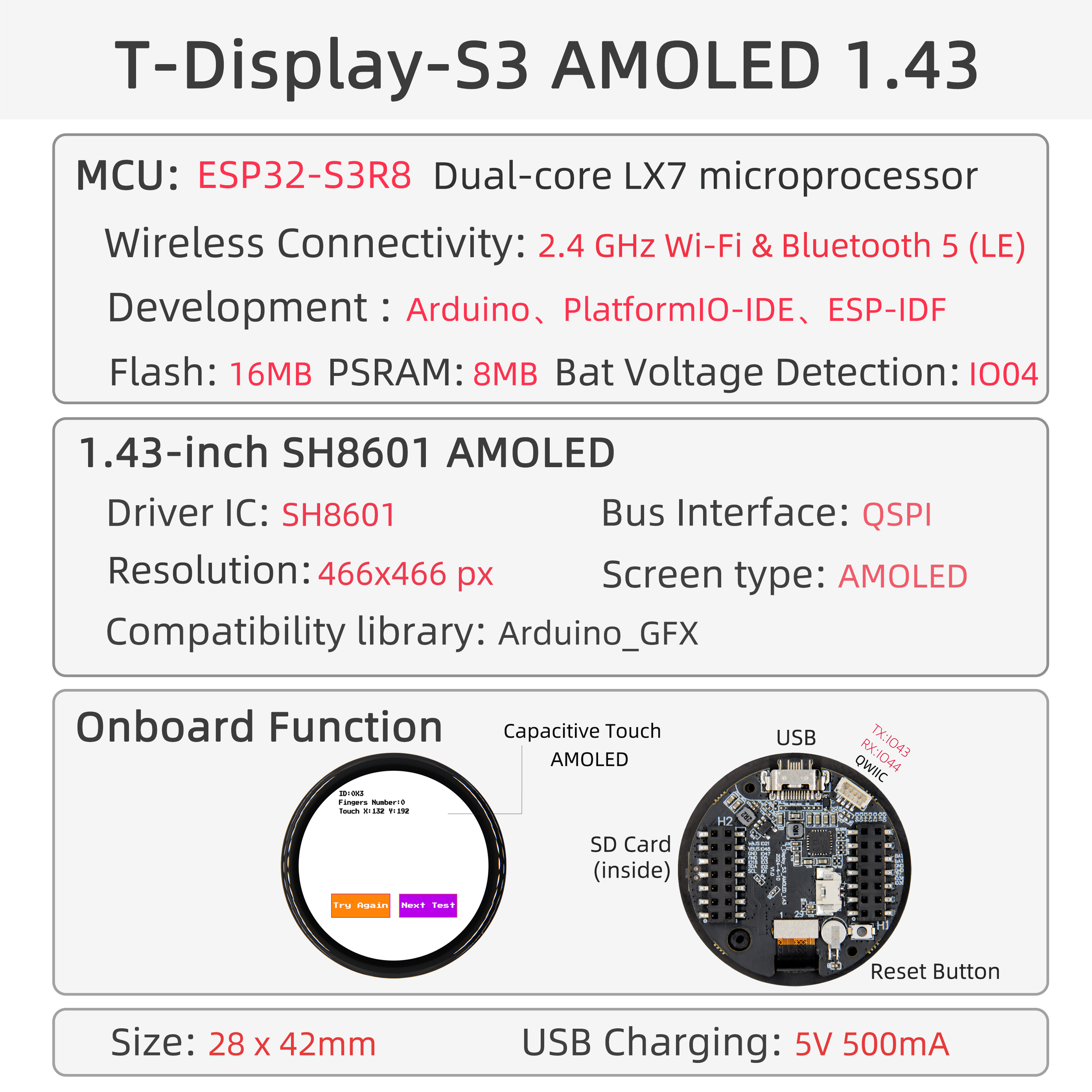
MCU
Screen
- Size: 1.43-inch AMOLED circular screen
- Resolution: 466x466px
- Type: AMOLED
- Driver IC: SH8601
- Compatible Libraries: Arduino_GFX
- Bus Protocol: QSPI
Touch
- Chip: FT3268
- Bus Protocol: I2C
Charging Chip
- Chip: SY6970
- Bus Protocol: I2C
- Other: The output waveform of this chip will be very unstable when powered by 5V without battery. It is necessary to connect a battery for use or use software to close the battery channel, in which case the situation will be alleviated.
RTC
- Chip: PCF8563
- Bus Protocol: I2C
Overview
| Component |
Description |
| MCU |
ESP32-S3R8 Dual-core LX7 microprocessor |
| FLASH |
16MB |
| PSRAM |
8MB |
| Screen |
1.43-inch SH8601 AMOLED |
| Touch |
FT3168 Capacitive Touch Screen |
| Bus |
QSPI |
| LoRa |
1276:868,915Mhz |
| Storage |
TF Card |
| Charging Chip |
SY6970 |
| RTC |
PCF8563 |
| Wireless |
2.4 GHz Wi-Fi & Bluetooth 5 (LE) |
| USB |
1 × USB Port and OTG (TYPE-C Interface) |
| IO Interface |
2 x 2.54mm pitch 2*7 extended IO interface |
| Expansion Interfaces |
1 × QWIIC interface + JST-GH 1.25MM interface + 1 x battery connector |
| Buttons |
1 x RESET button + 1 x BOOT button |
| Dimensions |
45x45x11mm |
Quick Start
Example Support
- Install Visual Studio Code according to your system.
- Open the "Extensions" sidebar in Visual Studio Code (or press Ctrl+Shift+X), search for the "PlatformIO IDE" extension and install it.
- While the extension is installing, download the project from GitHub. You can click the green "<> Code" button to download the main branch, or download a "Releases" version from the sidebar.
- After the extension installation is complete, open the Explorer sidebar (or press Ctrl+Shift+E), click "Open Folder", find the project code you just downloaded (the entire folder), click "Add", and the project files will be added to your workspace.
- Open the "platformio.ini" file in the project folder (PlatformIO should automatically open it after adding the folder). Under the "[platformio]" section, uncomment the line selecting the example program you want to upload (starting with "default_envs = xxx"). Then click the "√" at the bottom left to compile. If the compilation is successful, connect the board to your computer and click the "→" at the bottom left to upload.
Arduino
- Install Arduino IDE according to your system.
- Open the "example" directory in the project folder, select the example project folder, and open the file ending with ".ino" to open the Arduino IDE project workspace.
- Open the "Tools" menu -> "Board" -> "Boards Manager", find or search for "esp32", and install the board files by "Espressif Systems". Then return to the "Board" menu and select the board type under "ESP32 Arduino". The board type to choose is determined by the "board = xxx" header in the "[env]" section of the "platformio.ini" file. If the corresponding board is not available, you need to manually add the board from the "board" directory in the project folder.
- Open the "[File]" -> "[Preferences]" menu, find the "[Sketchbook location]" field. Copy and paste all library files and folders from the "libraries" directory in the project folder into the "libraries" folder at this location.
- Select the correct settings in the "Tools" menu as shown in the table below.
ESP32-S3
| Setting |
Value |
| Board |
ESP32S3 Dev Module |
| Upload Speed |
921600 |
| USB Mode |
Hardware CDC and JTAG |
| USB CDC On Boot |
Enabled |
| USB Firmware MSC On Boot |
Disabled |
| USB DFU On Boot |
Disabled |
| CPU Frequency |
240MHz (WiFi) |
| Flash Mode |
QIO 80MHz |
| Flash Size |
16MB (128Mb) |
| Core Debug Level |
None |
| Partition Scheme |
16M Flash (3MB APP/9.9MB FATFS) |
| PSRAM |
OPI PSRAM |
| Arduino Runs On |
Core 1 |
| Events Run On |
Core 1 |
- Select the correct port.
- Click the "√" in the top right corner to compile. If the compilation is successful, connect the board to your computer and click the "→" to upload.
- Micropython
- Arduino IDE
- Platform IO
Pin Overview
| AMOLED Screen Pins |
ESP32S3 Pins |
| SDIO0 |
IO11 |
| SDIO1 |
IO13 |
| SDIO2 |
IO14 |
| SDIO3 |
IO15 |
| SCLK |
IO12 |
| CS |
IO10 |
| RST |
IO17 |
| EN |
IO16 |
| Touch Chip Pins |
ESP32S3 Pins |
| INT |
IO9 |
| SDA |
IO7 |
| SCL |
IO6 |
| Power Chip Pins |
ESP32S3 Pins |
| SDA |
IO7 |
| SCL |
IO6 |
| Battery Measurement Pins |
ESP32S3 Pins |
| BATTERY_VOLTAGE_ADC_DATA |
IO4 |
| SD Card Pins |
ESP32S3 Pins |
| CS |
IO4 |
| MOSI |
IO39 |
| MISO |
IO40 |
| SCLK |
IO41 |
Power Consumption
| Firmware |
Program |
Description |
[T-Display-S3-AMOLED-1.43_V1.0][Light_Sleep_Wake_Up]_firmware_V1.0.0.bin |
Light Sleep Wake Up |
Power Consumption: 1282.8uA |
[T-Display-S3-AMOLED-1.43_V1.0][Deep_Sleep_Wake_Up]_firmware_V1.0.0.bin |
Deep Sleep Wake Up |
Power Consumption: 174.2uA |
FAQ
Q. I still don't know how to set up the programming environment after reading the above tutorial. What should I do?
A. If you still don't understand how to set up the environment after reading the above tutorial, you can refer to the LilyGo-Document documentation for setup instructions.
Q. Why does Arduino IDE prompt me to upgrade library files when I open it? Should I upgrade or not?
A. Choose not to upgrade library files. Different versions of library files may not be compatible with each other, so upgrading is not recommended.
Q. Why is there no serial data output from the "Uart" interface on my board? Is it broken?
A. Because the project file is configured by default to use the USB interface as Uart0 serial output for debugging, and the "Uart" interface is connected to Uart0, it won't output any data without configuration.
PlatformIO users: Open the project file "platformio.ini", change the option "-DARDUINO_USB_CDC_ON_BOOT=true" under "build_flags = xxx" to "-DARDUINO_USB_CDC_ON_BOOT=false" to use the external "Uart" interface normally.
Arduino users: Open the "Tools" menu, select USB CDC On Boot: "Disabled" to use the external "Uart" interface normally.
Q. Why does my board keep failing to upload programs?
A. Please hold down the "BOOT-0" button and try uploading again.
Projects
Resources
Dependent Libraries


 English