


 English
LILYGO T-Watch S3 Plus
Version Iteration:
| Version | Update date | Update description |
|---|---|---|
| T-Watch-S3-Plus_V1.0 | 2024-01-01 | Initial version, added GPS functionality |
Purchase Links
| Product | SOC | FLASH | PSRAM | Link |
|---|---|---|---|---|
| T-Watch S3 Plus | ESP32-S3 | 16M | 8M (Octal SPI) | Link |
Table of Contents
Description
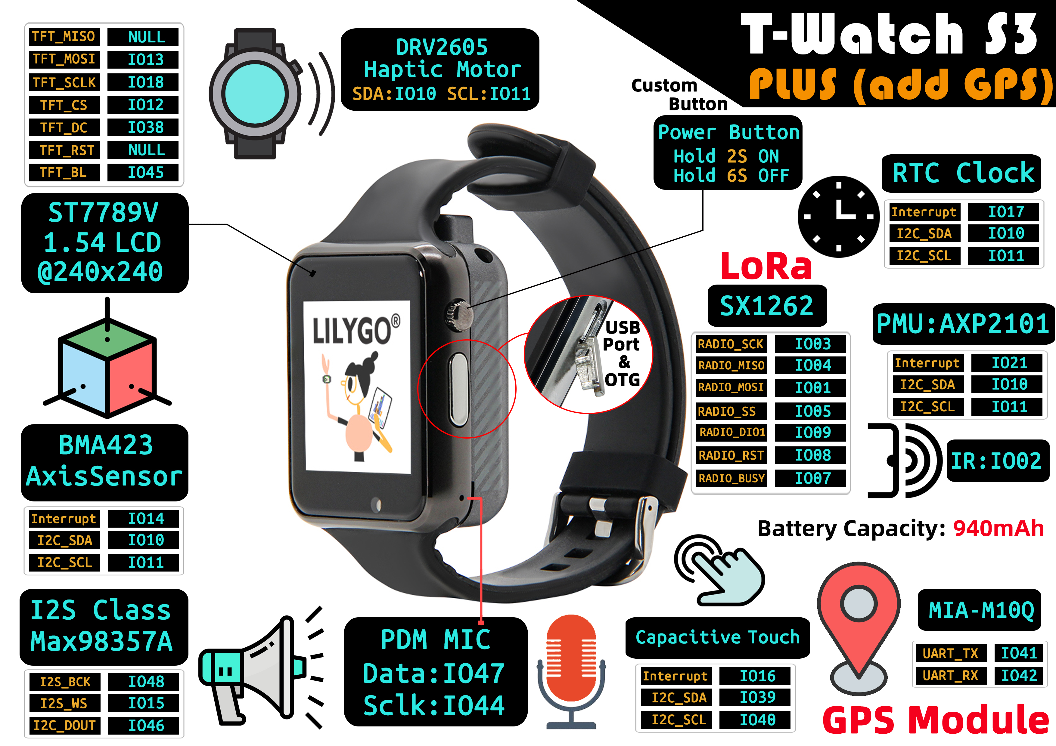
The T-Watch S3 Plus is an enhanced version based on the T-Watch S3, adding GPS functionality to create a multifunctional smart wearable device. It integrates high-performance hardware with wireless communication technology, suitable for sports health monitoring, remote interaction, and audio scenarios. Its core configuration includes a 1.54-inch 240x240 high-definition LCD display, paired with a BMA423 3-axis sensor and capacitive touch module, enabling precise motion tracking and responsive touch operations. Built-in Max98357A audio amplifier and PDM microphone support high-quality audio output and voice command input. Currently, the T-Watch S3 Plus offers two LoRa versions: SX1262 and SX1280, combined with the GPS module to achieve precise positioning and long-range, low-power wireless communication, suitable for IoT and smart wearable scenarios.
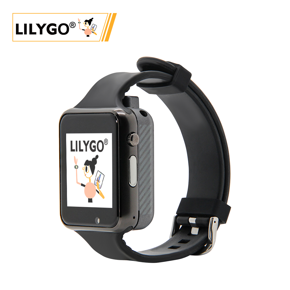
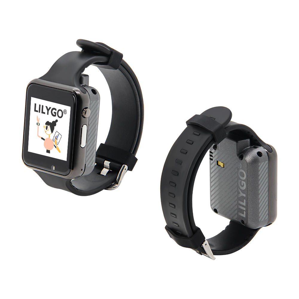
Preview
Physical Image
Pinout Diagram
Modules
MCU
- Chip: ESP32-S3
- PSRAM: 8M
- FLASH: 16M
- Other Notes: For more information, please visit Espressif Official ESP32-S3 Datasheet
Display
- Size: 1.54-inch LCD
- Resolution: 240×240px
- Display Type: LCD
- Bus Communication Protocol: SPI
Touch
- Type: Capacitive Touchscreen
- Bus Communication Protocol: I2C
Sensors
- 3-Axis Sensor: BMA423 (I2C)
- Motor Driver: DRV2605 (I2C)
Audio
- Audio Output: Max98357A (I2S)
- Audio Input: PDM Microphone
Communication Modules
- LoRa: SX1262/SX1280, supports 433~923MHz frequency bands
- GPS: Integrated GPS module
- Wi-Fi: 802.11 b/g/n
- Bluetooth: BLE 5.0
Power Management
- Chip: AXP2101 Highly Integrated Power Management Unit
Overview
✨ Hardware Features
| Feature | Parameter |
|---|---|
| SOC | Espressif ESP32-S3 |
| Flash | 16MB(QSPI) |
| PSRAM | 8MB (QSPI) |
| GNSS | UBlox MIA-M10Q |
| LoRa | Semtech SX1262 |
| Accelerometer | Bosch BMA423 |
| Real-Time Clock | NXP PCF8563 |
| Power Management | X-Powers AXP2101 |
| Haptic Driver | Texas Instruments DRV2605 |
| PDM Microphone | SPM1423HM4H-B |
| PCM Class D Amplifier | Analog Devices MAX98357A (3.2W Class D) |
| Capacitive Touch | FT6336U |
| IR Emitter | IR12-21C |
✨ Display Features
| Feature | Parameter |
|---|---|
| Resolution | 240 x 240 |
| Display Size | 1.3 inch |
| Surface Brightness | 450 cd/m² |
| Driver IC | ST7789V3 (SPI) |
| Contrast Ratio | 800:1 |
| Display Colors | 262K |
| Viewing Angle | Full View (IPS) |
| Operating Temperature | -20~70°C |
📍 Pin Mapping
| Name | GPIO Number | Idle |
|---|---|---|
| SDA | 10 | ❌ |
| SCL | 11 | ❌ |
| Touch Panel(FT6336U) SDA | 39 | ❌ |
| Touch Panel(FT6336U) SCL | 40 | ❌ |
| Touch Panel(FT6336U) Interrupt | 16 | ❌ |
| Touch Panel(FT6336U) Reset | Not Connected | ❌ |
| RTC(PCF8563) SDA | Shared I2C Bus | ❌ |
| RTC(PCF8563) SCL | Shared I2C Bus | ❌ |
| RTC(PCF8563) Interrupt | 17 | ❌ |
| Sensor(BMA423) Interrupt | 14 | ❌ |
| Sensor(BMA423) SDA | Shared I2C Bus | ❌ |
| Sensor(BMA423) SCL | Shared I2C Bus | ❌ |
| PCM Amplifier(MAX98357A) BCLK | 48 | ❌ |
| PCM Amplifier(MAX98357A) WCLK | 15 | ❌ |
| PCM Amplifier(MAX98357A) DOUT | 46 | ❌ |
| GNSS(MIA-M10Q) TX | 42 | ❌ |
| GNSS(MIA-M10Q) RX | 41 | ❌ |
| GNSS(MIA-M10Q) PPS | Not Connected | ❌ |
| LoRa(SX1262 or SX1280) SCK | 3 | ❌ |
| LoRa(SX1262 or SX1280) MISO | 4 | ❌ |
| LoRa(SX1262 or SX1280) MOSI | 1 | ❌ |
| LoRa(SX1262 or SX1280) Reset | 8 | ❌ |
| LoRa(SX1262 or SX1280) BUSY | 7 | ❌ |
| LoRa(SX1262 or SX1280) CS | 5 | ❌ |
| LoRa(SX1262 or SX1280) Interrupt | 9 | ❌ |
| Display CS | 12 | ❌ |
| Display MOSI | 13 | ❌ |
| Display MISO | Not Connected | ❌ |
| Display SCK | 18 | ❌ |
| Display DC | 38 | ❌ |
| Display Reset | Not Connected | ❌ |
| Display Backlight | 45 | ❌ |
| Charger(AXP2101) SDA | Shared I2C Bus | ❌ |
| Charger(AXP2101) SCL | Shared I2C Bus | ❌ |
| Charger(AXP2101) Interrupt | 21 | ❌ |
| Haptic Driver(DRV2605) SDA | Shared I2C Bus | ❌ |
| Haptic Driver(DRV2605) SCL | Shared I2C Bus | ❌ |
| PDM Microphone(SPM1423HM4H) SCK | 44 | ❌ |
| PDM Microphone(SPM1423HM4H) DATA | 47 | ❌ |
| IR Emitter | 2 | ❌ |
🧑🏼🔧 I2C Device Addresses
| Device | 7-bit Address | Shared Bus |
|---|---|---|
| Touch Panel FT6336U | 0x38 | ❌ Uses Wire1 |
| Accelerometer BMA423 | 0x19 | ✅️ |
| Power Management AXP2101 | 0x34 | ✅️ |
| Real-Time Clock PCF8563 | 0x51 | ✅️ |
| Haptic Driver DRV2605 | 0x5A | ✅️ |
⚡ Power Management Channels
| Channel | Peripheral |
|---|---|
| DC1 | ESP32-S3 |
| DC2 | Unused |
| DC3 | Unused |
| DC4 | Unused |
| DC5 | Unused |
| LDO1(VRTC) | Unused |
| ALDO1 | Unused |
| ALDO2 | Display Backlight |
| ALDO3 | Display and Touch |
| ALDO4 | LoRa |
| BLDO1 | GNSS |
| BLDO2 | DRV2605 Enable |
| DLDO1 | Unused |
| CPUSLDO | Unused |
| VBACKUP | RTC Coin Cell Battery |
- BLDO1 serves as GPS power (along with BOOT and RST buttons in the back case)
- DC3 was originally used as GPS power (without BOOT and RST buttons on the back cover)
⚡ Electrical Parameters
| Feature | Details |
|---|---|
| 🔗USB-C Input Voltage | 3.9V-6V |
| ⚡Charging Current | 0-1024mA ((Programmable)) |
| 🔋Battery Voltage | 3.7V |
| 🔋Battery Capacity | 1500mA ((5.55Wh)) |
⚠️ It is recommended to use a charging current below 130mA. Excessive charging current may damage the battery.
If not used for an extended period, please turn the battery switch to OFF.
⚡ Power Consumption Reference
| Mode | Wake-up Sources | Current |
|---|---|---|
| Light Sleep | Power Button + Boot Button + Touch Panel | 2.38mA |
| Light Sleep | Power Button + Boot Button | N/A |
| Deep Sleep | Power Button + Boot Button (Backup Power ON) | 530uA |
| Deep Sleep | Power Button + Boot Button (Backup Power OFF) | 460uA |
| Deep Sleep | Touch Panel | 1.08mA |
| Deep Sleep | Timer (Backup Power ON) | 510uA |
| Deep Sleep | Timer (Backup Power OFF) | 460uA |
| Shutdown | Only Backup Power Maintained | 50uA |
- T-Watch-S3-Plus does not have the touch reset pin connected, so if the touch screen is set to sleep, touch will not work.
Resources
Quick Start
Example Support
| Example | PlatformIO/Arduino | ESP-IDF | Description |
|---|---|---|---|
| Factory Program | ✓ | Factory Example | |
| (More examples please refer to GitHub repository) |
PlatformIO
- Install Visual Studio Code, choose the installation according to your system type.
- Open the "Extensions" in the Visual Studio Code sidebar (or use Ctrl+Shift+X to open extensions), search for the "PlatformIO IDE" extension and install it.
- During the extension installation, you can go to GitHub to download the project code. You can download the main branch code by clicking the green "<> Code" button, or download the "Releases" version from the sidebar.
- After the extension installation is complete, open the sidebar's Explorer (or use Ctrl+Shift+E to open it), click "Open Folder", find the recently downloaded project code folder (the entire folder), and click "Add". Now the project files are added to your workspace.
- Open the "platformio.ini" file in the project folder (PlatformIO will automatically open the "platformio.ini" for the corresponding folder), under the "[platformio]" section, uncomment to select the example program you want to flash (headed by "default_envs = xxx"), then click the "√" at the bottom left to compile. If the compilation is successful, connect the microcontroller to your computer, and click the "→" at the bottom left to flash.
Arduino
- Install Arduino IDE
- Install Arduino ESP32 V3.3.0-alpha1 or higher or the latest version
- Tip: Arduino Manager URL: https://espressif.github.io/arduino-esp32/package_esp32_dev_index.json
- Download LilyGoLib library
- Open
Arduino IDE->Sketch->Include Library->Add .ZIP Library->Select the library zip file downloaded in step 3 - Install LilyGoLib-ThirdParty
- Copy all directories from LilyGoLib-ThirdParty to the ArduinoIDE libraries directory. If there is no
librariesdirectory, please create it. - Please note: do not copy the
LilyGoLib-ThirdPartydirectory itself, but copy the folders inside theLilyGoLib-ThirdPartydirectory to the libraries directory. - How to find the library location on your computer, please see here
- Windows:
C:\Users\{Username}\Documents\Arduino - macOS:
/Users/{Username}/Documents/Arduino - Linux:
/home/{Username}/Arduino
- Windows:
- Copy all directories from LilyGoLib-ThirdParty to the ArduinoIDE libraries directory. If there is no
Please note that the libraries in LilyGoLib-ThirdParty are not necessarily the latest versions. Before confirming the hardware is working properly, please do not upgrade the dependent library versions.
ArduinoIDE will prompt that new library versions are available for upgrade every time it opens.
Please confirm normal operation before attempting to update to the latest versions. If you encounter issues, please revert to the dependent library versions that worked properly. The current dependent library version list can be viewed here
File->Examples->LilyGOLib->helloworldTools->Board->esp32, please select from the table below
| Arduino IDE Setting | Value |
|---|---|
| Board | LilyGo T-Watch-S3 |
| Port | Your port |
| USB CDC On Boot | Enabled |
| CPU Frequency | 240MHZ(WiFi) |
| Core Debug Level | None |
| USB DFU On Boot | Disable |
| Erase All Flash Before Sketch Upload | Disable |
| Events Run On | Core 1 |
| JTAG Adapter | Disable |
| Arduino Runs On | Core 1 |
| USB Firmware MSC On Boot | Disable |
| Partition Scheme | 16M Flash(3M APP/9.9MB FATFS) |
| Board Revision | Radio-SX1262 |
| Upload Mode | UART0/Hardware CDC |
| Upload Speed | 921600 |
| USB Mode | CDC and JTAG |
| USB Mode | CDC and JTAG |
- Board Revision Option, please select according to the actual purchased RF type. Current options include:
- Radio-SX1262(Sub 1G LoRa)
- Radio-SX1280(2.4G LoRa)
- Radio-CC1101(Sub 1G (G)MSK, 2(G)FSK, 4(G)FSK, ASK, OOK)
- Radio-LR1121(Sub 1G + 2.4G LoRa)
- Radio-SI4432(Sub 1G ISM)
- Select
Port - Click
Upload, wait for compilation and writing to complete - If unable to upload the program or the USB device keeps popping up on the computer, please manually put the device into download mode. How to enter download mode, please see here
- If there is no serial message output, please check if USB CDC ON Boot is set to Enabled.
- The board revision varies according to the actual RF module model. The current default version is SX1262.
- This library depends on the latest arduino-esp32 version. If it is lower than V3.3.0-alpha1, it will report an error.
T-Watch-S3-Plus Enter Download Mode
Download mode is only needed when the program does not allow code upload. Normally this step is not required.
🤖 The BOOT button and RST button for T-Watch-S3-Plus are reserved on the edge of the case. Please follow the steps below to put the device into download mode.
- Connect the development board via USB-C cable
- Press and hold the BOOT button, while still holding the BOOT button
- Release the RST button
- Release the BOOT button
- The USB port should be fixed and not blink again. You can click upload.
- Press the RST button to exit download mode
If the new code is successfully written but the device does not light up or has other issues, please use our factory test code to test whether the peripherals can work normally. Please jump here to download the firmware and write it for testing.
Development Platforms
FAQ
Q: What is the main difference between T-Watch S3 Plus and T-Watch S3?
A: T-Watch S3 Plus adds GPS functionality based on T-Watch S3, other hardware configurations are basically the same.Q: How to power on and off?
A: Press and hold the POWER button for 2 seconds to power on, hold for 6 seconds to power off. The BOOT button is a built-in button used to enter download mode.Q: Which LoRa frequency bands are supported?
A: Currently there are two versions: SX1262 and SX1280, supporting 433MHz~923MHz frequency bands. Please choose the appropriate version according to the regulations in your region.Q: How to develop watch applications?
A: It is recommended to use the TTGO_TWatch_Library, which provides rich watch UI components and sensor drivers for rapid watch application development.Q: What is the battery life?
A: Battery life depends on usage scenarios. Under normal usage conditions, it can last for several days. For specific times, please refer to actual test data.
Projects
Resources
- ESP32-S3 Datasheet
- BMA423 Datasheet
- AXP2101 Datasheet
- (More resources please refer to GitHub repository)