Version Iteration
| Version |
Update date |
Update description |
| T3-S3-MVSRBoard_V1.0 |
2024-11-06 |
Initial Version |
| T3-S3-MVSRBoard_V1.1 |
2025-03-18 |
Changed Microphone Model |
Purchase Links
| Product |
SOC |
FLASH |
PSRAM |
Link |
| T3-S3 MVSR Board |
ESP32-S3 |
4MB |
2MB |
LILYGO Store |
Table of Contents
Description
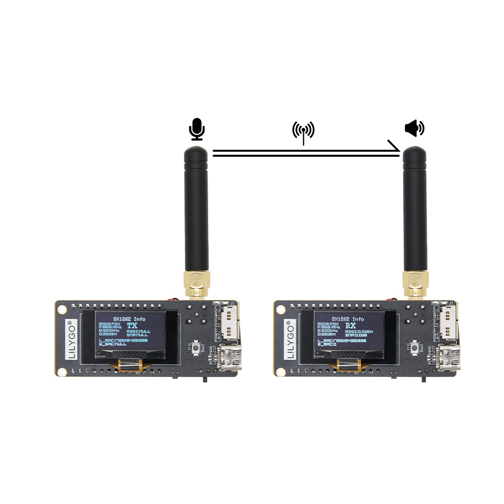
The T3-S3 MVSR version is based on the T3-S3 main board with an extended module featuring vibration motor, microphone, speaker, and RTC functions. The main application of this version is for LoRa voice transmission and reception. This extended version currently supports both SX1262 and SX1280 models of the T3S3 motherboard. The SX1262 version uses FSK modulation, while the SX1280 version uses LoRa modulation. Corresponding test demos are available on GitHub for your development reference. Of course, this extended version can also be used for AI voice interaction functions, MP3 playback, and more.
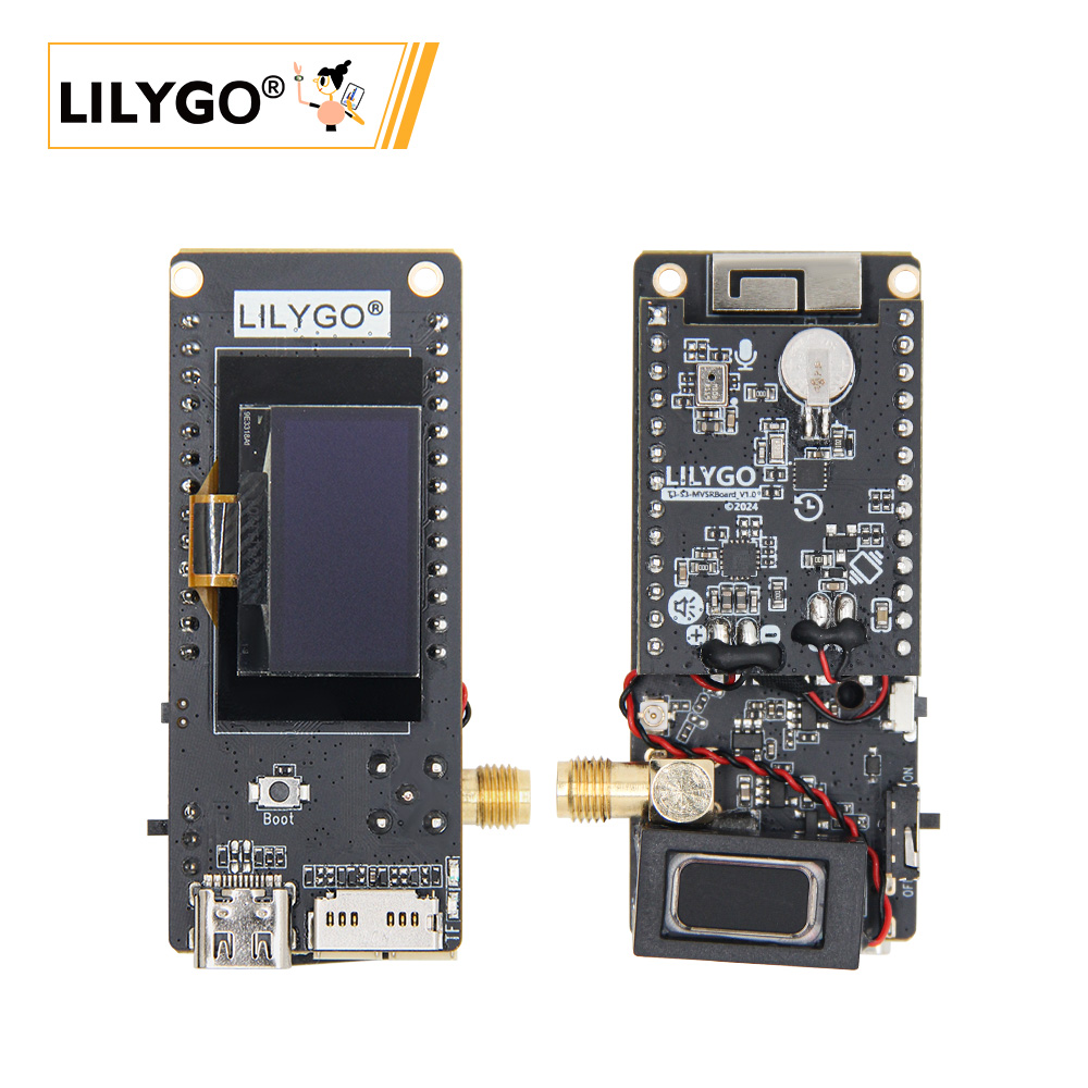
Preview
Physical Image
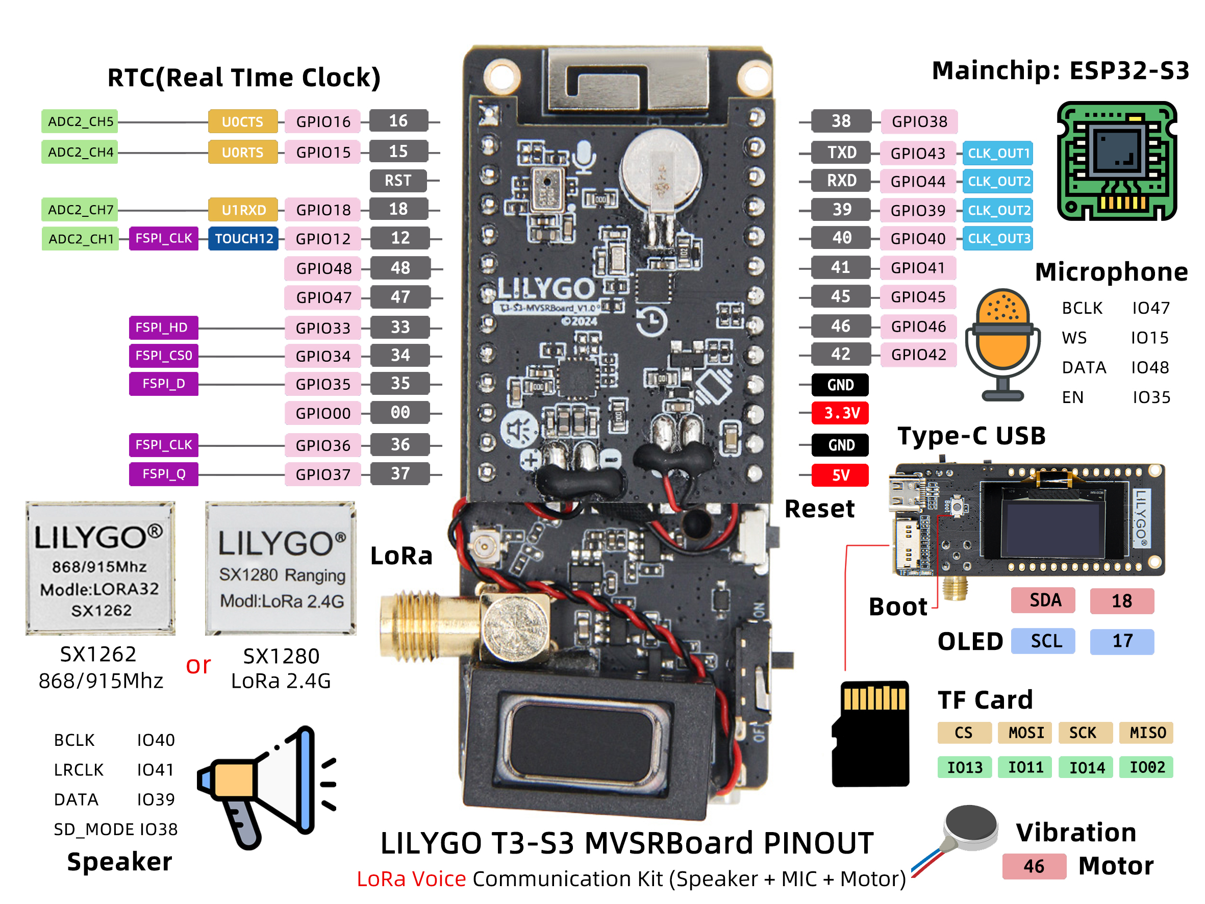
Pinout Diagram
Modules
MCU
- Chip: ESP32-S3FH4R2
- PSRAM: 2MB (OPI PSRAM)
- FLASH: 4MB
- Wireless: 2.4GHz Wi-Fi + Bluetooth 5.0
Speaker
Microphone
T3-S3-MVSRBoard_V1.0 Version
T3-S3-MVSRBoard_V1.1 Version
RTC
Wireless Communication
- LoRa Module: SX1262 / SX1280
- Frequency Bands: 868/915MHz (SX1262) / 2.4GHz (SX1280)
- Modulation: FSK (SX1262) / LoRa (SX1280)
Function Expansion
- Vibration Motor: Haptic feedback
- Storage: TF Card Expansion
Overview
The T3-S3-MVSRBoard is a backplane design for the T3-S3_V1.2 main board, featuring onboard speaker and microphone expansion functions with extremely low static current. Additionally, it includes vibration and RTC (Real-Time Clock) functions.
| Component |
Description |
| MCU |
ESP32-S3FH4R2 Dual-core LX7 |
| FLASH |
4MB |
| PSRAM |
2MB |
| Audio Input |
MP34DT05-A PDM Microphone |
| Audio Output |
MAX98357A I2S Speaker |
| LoRa |
SX1262 (868/915MHz) / SX1280 (2.4GHz) |
| RTC |
PCF85063ATL Real-Time Clock (I2C) |
| Vibration |
Haptic Vibration Motor |
| Storage |
TF Card Expansion |
| Wireless |
2.4GHz Wi-Fi + Bluetooth 5.0 |
| USB |
1 × USB Port (TYPE-C Connector) |
| GPIO Interface |
2.54mm pitch 2×20 Expansion IO Interface |
| Display |
I2C OLED (Optional) |
| Buttons |
1 x RESET Button + 1 x BOOT Button |
| Power Input |
5V/500mA |
| Mounting Holes |
2 × 2mm Positioning Holes |
| Dimensions |
66 × 27 × 15 mm |
Quick Start
Example Support
- Install Visual Studio Code, choose the installation according to your system type.
- Open the "Extensions" in the Visual Studio Code sidebar (or use Ctrl+Shift+X to open extensions), search for the "PlatformIO IDE" extension and download it.
- During the extension installation, you can go to GitHub to download the code. You can download the main branch code by clicking the green "<> Code" button, or download the "Releases" version from the sidebar.
- After the extension installation is complete, open the sidebar's Explorer (or use Ctrl+Shift+E to open it), click "Open Folder", find the recently downloaded project code folder (the entire folder), and click "Add". Now the project files are added to your workspace.
- Open the "platformio.ini" file in the project folder (PlatformIO will automatically open the "platformio.ini" for the corresponding folder), under the "[platformio]" section, uncomment to select the example program you want to flash (headed by "default_envs = xxx"), then click the "√" at the bottom left to compile. If the compilation is successful, connect the microcontroller to your computer, and click the "→" at the bottom left to flash.
Arduino
- Install Arduino IDE, choose the installation according to your system type.
- Open the "example" directory in the project folder, select the example project folder, and open the file ending with ".ino" to open the Arduino IDE project workspace.
- Open the "Tools" menu in the top right corner -> Select "Board" -> "Board Manager", find or search for "esp32", and download the board files by "Espressif Systems". Then return to the "Board" menu and select the "ESP32S3 Dev Module" board.
- Open the menu "File" -> "Preferences", find the "Sketchbook location" field, and copy all library files along with their folders from the "libraries" folder in the project directory to the "libraries" folder in this location.
- Select the correct settings in the "Tools" menu as shown in the table below.
ESP32-S3
| Setting |
Value |
| Board |
ESP32S3 Dev Module |
| Upload Speed |
921600 |
| USB Mode |
Hardware CDC and JTAG |
| USB CDC On Boot |
Enabled |
| USB Firmware MSC On Boot |
Disabled |
| USB DFU On Boot |
Disabled |
| CPU Frequency |
240MHz (WiFi) |
| Flash Mode |
QIO 80MHz |
| Flash Size |
16MB (128Mb) |
| Core Debug Level |
None |
| Partition Scheme |
16M Flash (3MB APP/9.9MB FATFS) |
| PSRAM |
OPI PSRAM |
| Arduino Runs On |
Core 1 |
| Events Run On |
Core 1 |
- Select the correct port.
- Click the "√" in the top right corner to compile. If the compilation is successful, connect the microcontroller to your computer, and click the "→" in the top right corner to flash.
- Micropython
- Arduino IDE
- Platform IO
- VS Code
Pin Overview
| Speaker Pins |
ESP32S3 Pins |
| BCLK |
IO40 |
| LRCLK |
IO41 |
| DATA |
IO39 |
| SD_MODE |
IO38 |
| Vibration Motor Pins |
ESP32S3 Pins |
| DATA |
IO46 |
| RTC Pins |
ESP32S3 Pins |
| SDA |
IO42 |
| SCL |
IO45 |
| INT |
IO16 |
| SX126x Pins |
ESP32S3 Pins |
| CS |
IO7 |
| RST |
IO8 |
| SCLK |
IO5 |
| MOSI |
IO6 |
| MISO |
IO3 |
| DIO1 |
IO33 |
| BUSY |
IO34 |
| SX127x Pins |
ESP32S3 Pins |
| CS |
IO7 |
| RST |
IO8 |
| SCLK |
IO5 |
| MOSI |
IO6 |
| MISO |
IO3 |
| DIO0 |
IO9 |
| DIO1 |
IO33 |
| DIO2 |
IO34 |
| DIO3 |
IO21 |
| DIO4 |
IO10 |
| DIO5 |
IO36 |
| SX128x Pins |
ESP32S3 Pins |
| CS |
IO7 |
| RST |
IO8 |
| SCLK |
IO5 |
| MOSI |
IO6 |
| MISO |
IO3 |
| DIO1 |
IO9 |
| BUSY |
IO36 |
| TX |
IO10 |
| RX |
IO21 |
T3-S3-MVSRBoard_V1.0 Version
| Microphone Pins |
ESP32S3 Pins |
| BCLK |
IO47 |
| WS |
IO15 |
| DATA |
IO48 |
| EN |
IO35 |
T3-S3-MVSRBoard_V1.1 Version
| Microphone Pins |
ESP32S3 Pins |
| LRCLK |
IO15 |
| DATA |
IO48 |
| EN |
IO35 |
Power Consumption
| Parameter |
Specification |
| Sample Rate |
8-48 kHz |
| Bit Depth |
16-bit |
| Signal-to-Noise Ratio |
>90 dB |
FAQ
Q. How to adjust external antenna resistance?
A. Refer to the arrow in the image below to replace the resistor to adjust the external antenna resistance:

Q. What's the difference between SX1262 and SX1280 versions?
A. SX1262 supports 868/915MHz frequency bands and uses FSK modulation; SX1280 supports 2.4GHz frequency band and uses LoRa modulation.
Q. Which audio formats are supported?
A. Supports common audio formats like WAV, MP3, etc., and can be extended with software decoding libraries.
Q. What is the LoRa voice communication range?
A. Under ideal conditions, voice communication range can reach several kilometers, depending on environmental factors and antenna configuration.
Q. Does it support real-time voice transmission?
A. Supports real-time voice acquisition, compression, and LoRa transmission, enabling voice intercom functionality.
Projects
Resources
Dependent Libraries


 English