


 English
LILYGO T-Camera Plus S3
Version History:
| Version | Update Date | Update Description |
|---|---|---|
| T-CameraPlus-S3_V1.0-V1.1 | 2023-10-23 | Initial Version |
| T-CameraPlus-S3_V1.2 | 2025-04-17 | Improved WiFi performance, updated microphone model, modified pin numbers, optimized PCB routing |
Purchase Link
| Product | SOC | FLASH | PSRAM | Link |
|---|---|---|---|---|
| T-CameraPlus-S3_V1.2 | ESP32S3 | 16M | 8M | LILYGO Mall |
Table of Contents
Description
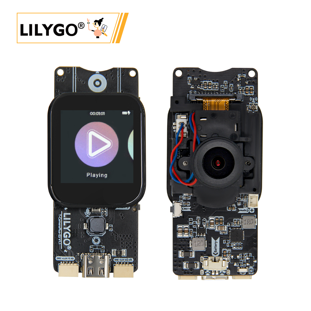
The T-CameraPlus-S3 is a versatile smart hardware development board based on the ESP32-S3 main control chip. It integrates a high-performance camera module (OV2640/OV5640 optional), an LCD display (with touch), and a MAX98357A audio chip. Equipped with 16MB Flash and 8MB PSRAM, it can efficiently process image, video, and audio data. It supports dual-mode audio input and output (microphone and digital audio interface), features TF card expansion storage, QWIIC interface (compatible with I²C device expansion), and a battery management module. The hardware design is compatible with various sensors and peripherals, enabling collaborative work between the camera, display, and audio modules through protocols like SPI and I²C, meeting developers' flexible needs in AIoT, edge computing, and other fields. It comes pre-installed with an LVGL-based UI system supporting file management, music playback, recording, camera projection, and other functions.
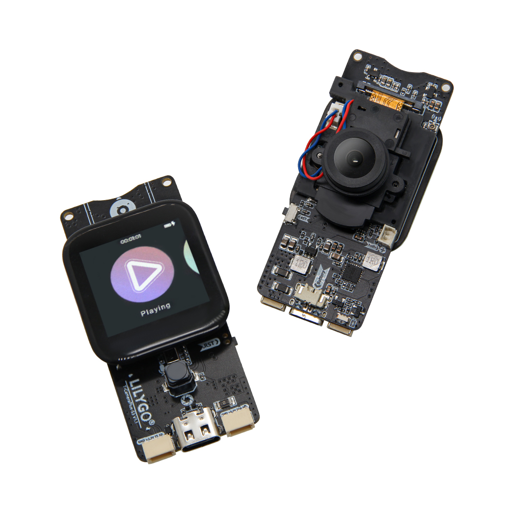
Preview
Physical Images
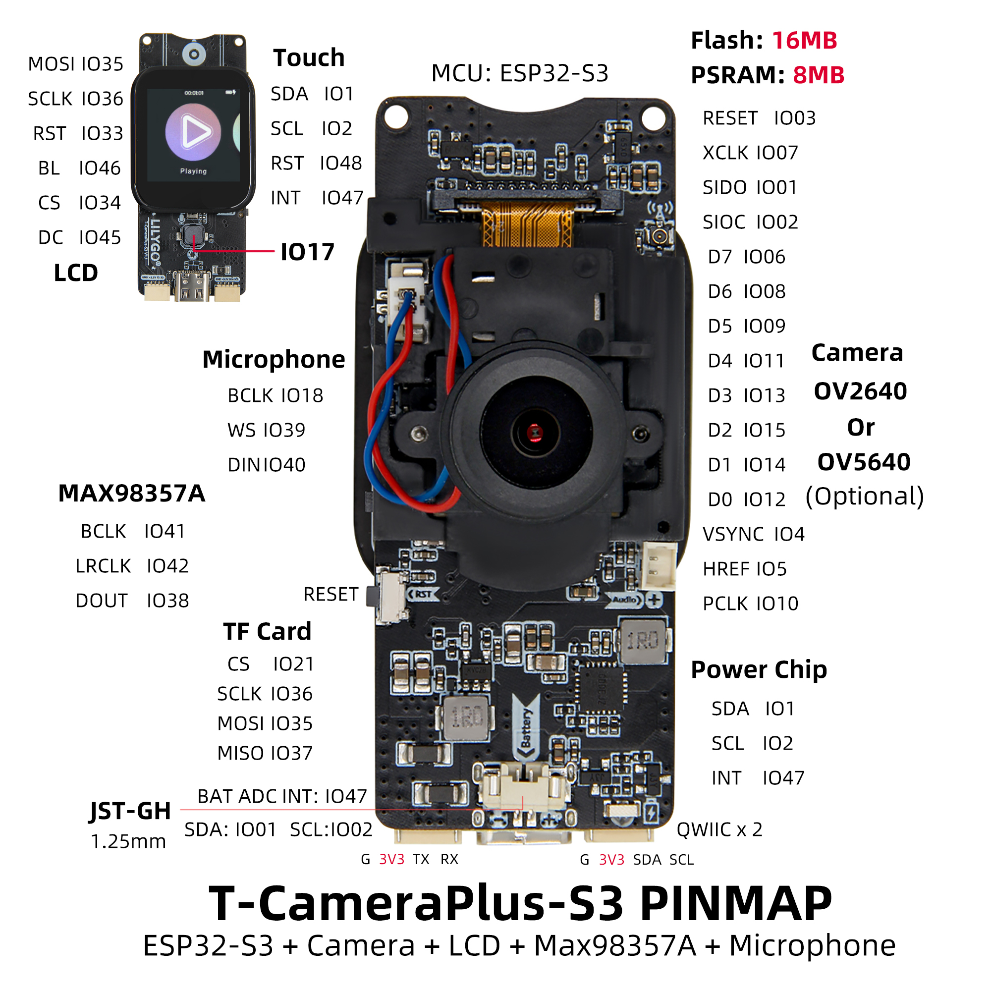
Pinout Diagram
Modules
MCU
- Chip: ESP32-S3
- PSRAM: 8M
- FLASH: 16M
- Related Information:
Espressif
Screen
- Model: fp-133h01d
- Size: 1.3-inch
- Resolution: 240x240px
- Type: TFT
- Driver IC: ST7789V
- Bus Protocol: Standard SPI
- Dependent Libraries:
Arduino_GFX-1.3.7
lvgl-8.3.5
JPEGDEC-1.2.8
MiniTV
TFT_eSPI
Touch
- Chip: CST816S
- Bus Protocol: I2C
- Dependent Libraries:
cst816t-1.5.0
Arduino_DriveBus-1.1.16
Speaker
- Chip: MAX98357A
- Bus Protocol: I2S
- Other Notes: Default configuration is Left/2 + Right/2 channels, 9dB gain. To change configuration, modify resistors according to instructions on the T-CameraPlus-S3 schematic. Recommended speaker specs: max rated power 3.2W, impedance around 4 ohms, below 8 ohms.
- Related Information:
MAX98357A
- Dependent Libraries:
arduino-libhelix-0.8.1
ESP32-audioI2S-3.0.6
Microphone
T-CameraPlus-S3_V1.0-V1.1 Version
- Chip: MSM261S4030H0R
- Bus Protocol: I2S
- Other Notes: Default configuration is right channel. To change configuration, modify resistors according to instructions on the T-CameraPlus-S3 schematic.
- Related Information:
MSM261S4030H0R- Dependent Libraries:
DFRobot_MSM261
Arduino_DriveBus-1.1.16
T-CameraPlus-S3_V1.2 Version
- Chip: MP34DT05-A
- Bus Protocol: PDM
- Other Notes: Default configuration is right channel. To change configuration, modify resistors according to instructions on the T-CameraPlus-S3 schematic.
- Related Information:
MP34DT05-A- Dependent Libraries:
Arduino_DriveBus-1.1.16
Camera
- Camera Model: OV2640
- IR Filter Driver: AP1511B
- Related Information:
OV2640_Hardware_Application_V1.04
OV2640_Software_Application_V1.03
Power Management IC
- Chip: SY6970
- Related Information:
AN_SY6970
EVB_SY6970 - Dependent Libraries:
XPowersLib-0.2.1
Arduino_DriveBus-1.1.16
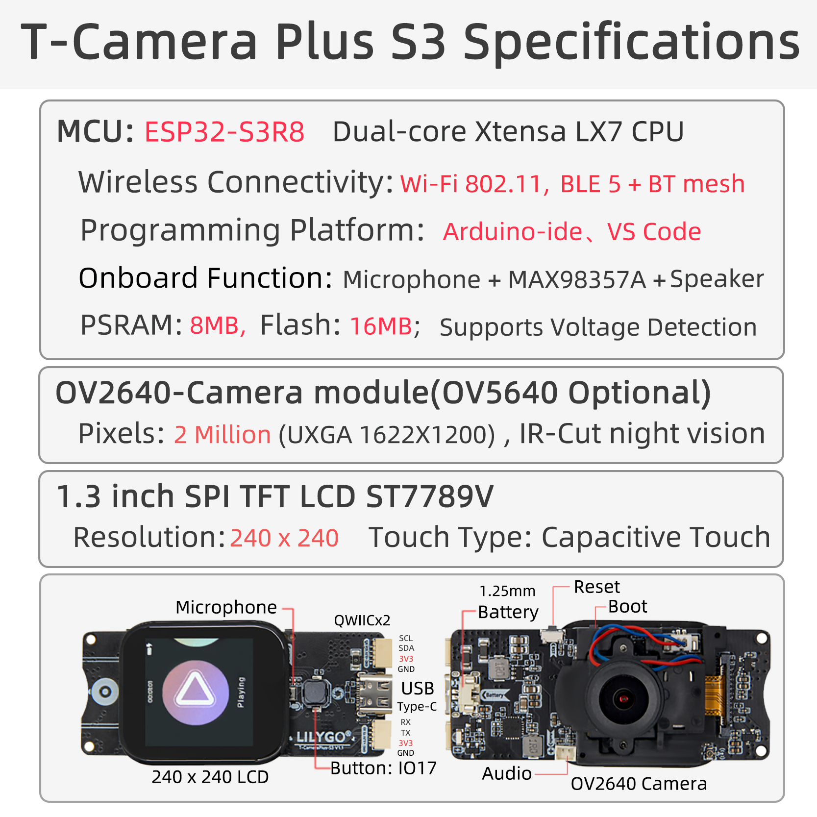
Overview
| Component | Description |
|---|---|
| MCU | ESP32-S3R8 Dual-core Xtensa LX7 CPU |
| FLASH | 16MB |
| PSRAM | 8MB |
| Screen | 1.3-inch ST7789V TFT LCD (240×240) |
| Touch | CST816S Capacitive Touch Screen |
| Camera | OV2640/OV5640 (Optional) |
| Storage | TF Card |
| Audio Output | MAX98357A Speaker |
| Audio Input | MP34DT05-A Microphone |
| Power Management | AXPM65611 + BQ25896 + SY6970 |
| Wireless | 2.4 GHz Wi-Fi & Bluetooth 5 (LE) |
| USB | 1 × USB Port and OTG (TYPE-C Interface) |
| IO Interface | 2×13 Dual-row Expansion Interface |
| Expansion Interfaces | TF Card + 2×STEMMA QT/QWIIC + JST-GH 1.25MM |
| Buttons | RESET + BOOT + IO17 Function Button |
| Mounting Holes | 4 × 2mm Positioning Holes |
| Dimensions | 60×32×12mm |
Quick Start
Example Support
| Example | [Platformio IDE][espressif32-v6.5.0][Arduino IDE][esp32_v2.0.14] |
[vscode][esp-idf-v5.4.0] |
Description | Picture |
|---|---|---|---|---|
| Wifi_Scan | ||||
| Lvgl_UI | Factory Firmware | |||
| Wifi_Music | ||||
| SD_Music | ||||
| DMIC_ReadData | ||||
| SD_DMIC | ||||
| TFT | ||||
| IIC_Scan_2 | ||||
| Camera_WebServer | ||||
| CST816D | ||||
| GFX_Test | ||||
| SY6970 | ||||
| SD_MJPEG | ||||
| Camera_Screen | ||||
| Camera_Screen_OV5640_Auto_Focus | ||||
| Camera_WebServer_OV5640_Auto_Focus | ||||
| Voice_Speaker | ||||
| iic_scan | ||||
| afe |
| Firmware | Description | Picture |
|---|---|---|
| Lvgl_UI(V1.0-V1.1) | ||
| Lvgl_UI(V1.2) |
PlatformIO
- Install Visual Studio Code according to your system.
- Open the "Extensions" sidebar in Visual Studio Code (or press Ctrl+Shift+X), search for the "PlatformIO IDE" extension and install it.
- While the extension is installing, download the project from GitHub. You can click the green "<> Code" button to download the main branch, or download a "Releases" version from the sidebar.
- After the extension installation is complete, open the Explorer sidebar (or press Ctrl+Shift+E), click "Open Folder", find the project code you just downloaded (the entire folder), click "Add", and the project files will be added to your workspace.
- Open the "platformio.ini" file in the project folder (PlatformIO should automatically open it after adding the folder). Under the "[platformio]" section, uncomment the line selecting the example program you want to upload (starting with "default_envs = xxx"). Then click the "√" at the bottom left to compile. If the compilation is successful, connect the board to your computer and click the "→" at the bottom left to upload.
Arduino
Install Arduino IDE according to your system.
Open the "example" directory in the project folder, select the example project folder, and open the file ending with ".ino" to open the Arduino IDE project workspace.
Open the "Tools" menu -> "Board" -> "Boards Manager", find or search for "esp32", and install the board files by "Espressif Systems". Then return to the "Board" menu and select the board type under "ESP32 Arduino". The board type to choose is determined by the "board = xxx" header in the "[env]" section of the "platformio.ini" file. If the corresponding board is not available, you need to manually add the board from the "board" directory in the project folder.
Open the "[File]" -> "[Preferences]" menu, find the "[Sketchbook location]" field. Copy and paste all library files and folders from the "libraries" directory in the project folder into the "libraries" folder at this location.
Select the correct settings in the "Tools" menu as shown in the table below.
| Setting | Value |
|---|---|
| Board | ESP32S3 Dev Module |
| Upload Speed | 921600 |
| USB Mode | Hardware CDC and JTAG |
| USB CDC On Boot | Enabled |
| USB Firmware MSC On Boot | Disabled |
| USB DFU On Boot | Disabled |
| CPU Frequency | 240MHz (WiFi) |
| Flash Mode | QIO 80MHz |
| Flash Size | 16MB (128Mb) |
| Core Debug Level | None |
| Partition Scheme | 16M Flash (3MB APP/9.9MB FATFS) |
| PSRAM | QSPI PSRAM |
| Arduino Runs On | Core 1 |
| Events Run On | Core 1 |
Select the correct port.
Click the "√" in the top right corner to compile. If the compilation is successful, connect the board to your computer and click the "→" to upload.
ESP-IDF Visual Studio Code
Install Visual Studio Code according to your system.
Open the "Extensions" sidebar in Visual Studio Code (or press Ctrl+Shift+X), search for the "ESP-IDF" extension and install it.
While the extension is installing, clone the repository using the git command:
git clone --recursive https://github.com/Xinyuan-LilyGO/T-CameraPlus-S3.gitUse "--recursive" during cloning. If you forgot to add it, you need to initialize the submodules later:
git submodule update --init --recursiveDownload and install ESP-IDF v5.4.1, note the installation path. Open the previously installed "ESP-IDF" extension and open "Configure ESP-IDF extension", select the "USE EXISTING SETUP" menu, choose the "Search ESP-IDF in system" option, and correctly configure the previously noted installation paths:
- ESP-IDF directory (IDF_PATH):
Your installation path\Espressif\frameworks\esp-idf-v5.4 - ESP-IDF Tools directory (IDF_TOOLS_PATH):
Your installation path\Espressif
Click "Install" at the bottom right to install the framework.
- ESP-IDF directory (IDF_PATH):
Click the ESP-IDF extension menu "SDK Configuration Editor" in the Visual Studio Code bottom menu bar. Search for the "Select the example to build" field and select the project you want to compile. Then search for the "Select the camera type" field and select the camera type on your board. Click Save.
Click "Set Espressif device target" in the Visual Studio Code bottom menu bar and select ESP32S3. Click "Build Project" in the bottom menu bar and wait for the build to complete. Then click "Select port to use" in the bottom menu bar, followed by "Flash Project" in the bottom menu bar to upload the program.
Development Platforms
Pin Overview
T-CameraPlus-S3_V1.0-V1.1 Version
| LCD Pin | ESP32S3 Pin |
|---|---|
| MOSI | IO35 |
| SCLK | IO36 |
| RST | IO33 |
| BL | IO46 |
| CS | IO34 |
| DC | IO45 |
| I2S Microphone MSM261S4030H0R Pin | ESP32S3 Pin |
|---|---|
| BCLK | IO18 |
| WS | IO39 |
| DATA | IO40 |
| Amplifier MAX98357A Pin | ESP32S3 Pin |
|---|---|
| BCLK | IO41 |
| LRCLK | IO42 |
| DATA | IO38 |
| SD Card Pin | ESP32S3 Pin |
|---|---|
| CS | IO21 |
| SCLK | IO36 |
| MOSI | IO35 |
| MISO | IO37 |
| Power Chip SY6970 Pin | ESP32S3 Pin |
|---|---|
| SDA | IO1 |
| SCL | IO2 |
| INT | IO47 |
| Camera OV2640 Pin | ESP32S3 Pin |
|---|---|
| RESET | IO3 |
| XCLK | IO7 |
| SIDO | IO1 |
| SIOC | IO2 |
| D7 | IO6 |
| D6 | IO8 |
| D5 | IO9 |
| D4 | IO11 |
| D3 | IO13 |
| D2 | IO15 |
| D1 | IO14 |
| D0 | IO12 |
| VSYNC | IO4 |
| HREF | IO5 |
| PCLK | IO10 |
| Touch Chip Pin | ESP32S3 Pin |
|---|---|
| SDA | IO1 |
| SCL | IO2 |
| RST | IO48 |
| INT | IO47 |
T-CameraPlus-S3_V1.2 Version
| LCD Pin | ESP32S3 Pin |
|---|---|
| MOSI | IO34 |
| SCLK | IO35 |
| BL | IO46 |
| CS | IO36 |
| DC | IO45 |
| PDM Microphone MP34DT05TR Pin | ESP32S3 Pin |
|---|---|
| LRCLK | IO40 |
| DATA | IO38 |
| Amplifier MAX98357A Pin | ESP32S3 Pin |
|---|---|
| BCLK | IO41 |
| LRCLK | IO42 |
| DATA | IO39 |
| SD Card Pin | ESP32S3 Pin |
|---|---|
| CS | IO21 |
| SCLK | IO35 |
| MOSI | IO34 |
| MISO | IO48 |
| Power Chip SY6970 Pin | ESP32S3 Pin |
|---|---|
| SDA | IO33 |
| SCL | IO37 |
| Camera OV2640 Pin | ESP32S3 Pin |
|---|---|
| XCLK | IO7 |
| SIDO | IO1 |
| SIOC | IO2 |
| D7 | IO6 |
| D6 | IO8 |
| D5 | IO9 |
| D4 | IO11 |
| D3 | IO13 |
| D2 | IO15 |
| D1 | IO14 |
| D0 | IO12 |
| VSYNC | IO3 |
| HREF | IO5 |
| PCLK | IO10 |
| PWDN | IO4 |
| Touch Chip Pin | ESP32S3 Pin |
|---|---|
| SDA | IO33 |
| SCL | IO37 |
| INT | IO47 |
| OV2640 IR Filter Control Pin | ESP32S3 Pin |
|---|---|
| AP1511B_FBC | IO16 |
| KEY1 Button Pin | ESP32S3 Pin |
|---|---|
| KEY1 | IO17 |
Related Tests
| Firmware | Program | Description | Picture |
|---|---|---|---|
| Deep_Sleep_Wake_Up | Deep_Sleep_Wake_Up | Average Current Consumption: 1.7mA. For more information, see Power Consumption Test Log |
FAQ
Q. What are the main application scenarios for the T-Camera Plus S3?
A. Suitable for smart surveillance, video doorbells, IoT visual interaction, multimedia terminals, AI image recognition, and other scenarios requiring camera and display functions.Q. Does it come pre-installed with a program?
A. It comes pre-installed with an LVGL-based UI program supporting file management, music playback, recording, camera projection, etc. If not pre-installed, you need to manually flash the "Lvgl_UI" example program.Q. Which camera modules are supported?
A. Supports OV2640 and OV5640 camera modules. Users can choose different resolution cameras according to their needs.Q. How is the audio functionality?
A. Integrates a MAX98357A audio amplifier to drive the speaker, and an MP34DT05-A digital microphone, supporting high-quality audio playback and recording.Q. How to expand external devices?
A. You can quickly connect compatible sensors via the 2 STEMMA QT/QWIIC interfaces, or connect other peripherals via the 2×13 dual-row expansion interface.
Projects
Resources
- ESP32-S3 Datasheet
- MAX98357A Datasheet
- MP34DT05-A Datasheet
- SY6970 Datasheet
- SY6970 Application Note