


 English
LILYGO T-2Can
Version History:
| Version | Update date | Update description |
|---|---|---|
| T-2Can_V1.0 | Initial Version |
Purchase Links
| Product | SOC | FLASH | PSRAM | Link |
|---|---|---|---|---|
| T-2Can | ESP32-S3-WROOM-1U | 16MB | 8MB (OPI PSRAM) | LILYGO Mall |
Table of Contents
Description
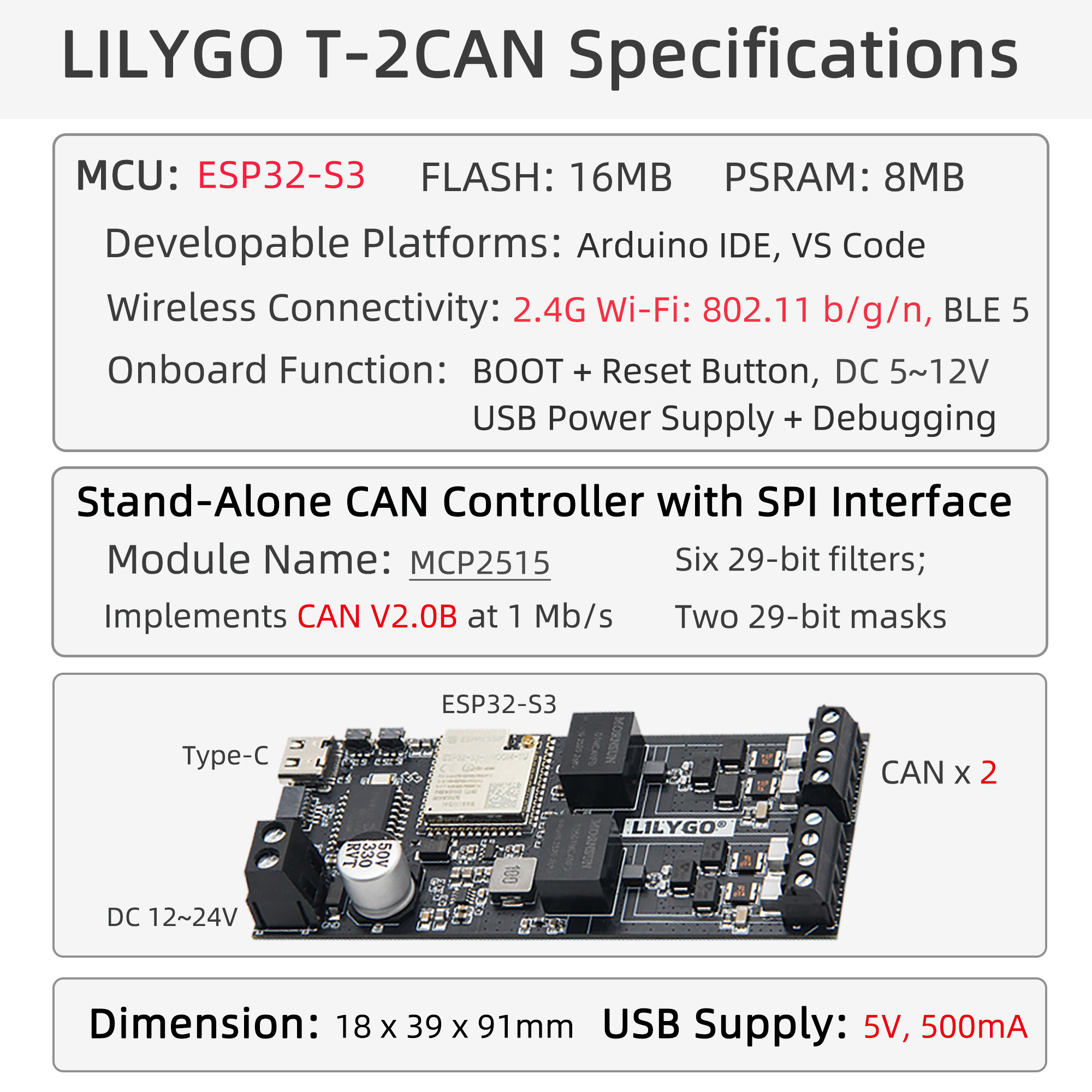
LILYGO T-2CAN is a high-performance, compact embedded communication module based on the powerful ESP32-S3 microcontroller (integrated with Wi-Fi and Bluetooth BLE wireless connectivity), and innovatively integrates dual independent MCP2515 CAN bus controllers. This module strictly adheres to the CAN 2.0B protocol standard, supports communication rates up to 1 Mb/s, and provides two completely independent CAN channel interfaces (including CAN_H, CAN_L, signal ground SGND, and power ground DGND), meeting industrial-grade communication requirements.
Core Features
- Dual Independent CAN Interfaces: Implemented through two MCP2515 chips, each equipped with 6 29-bit acceptance filters and 2 29-bit acceptance masks, ensuring high-reliability data filtering and transmission.
- Powerful Main Control: ESP32-S3 provides ample processing power and Wi-Fi/BLE wireless connectivity options, facilitating the construction of networked applications.
- Industrial-grade Design: Supports wide-range DC 12-24V power input, features signal isolation design (SGND/DGND), enhancing anti-interference capability.
- Rich Interfaces: Provides standard SPI interface connection to main control, integrated USB Type-C (power/programming), IPEX antenna interface, QWIIC expansion interface, and reset/boot buttons.
- Compact Size: Approximately 18 x 39 x 91 mm, easy to integrate.
Preview
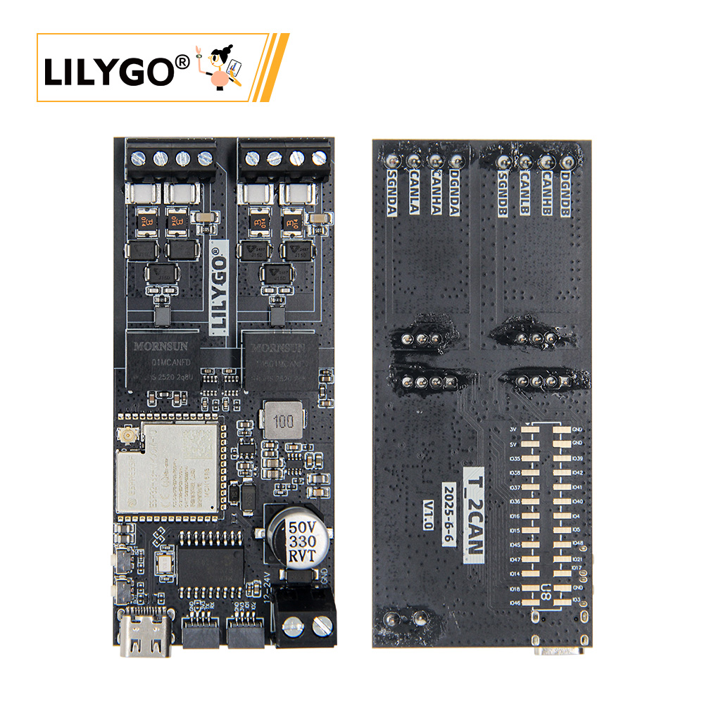
Physical Image

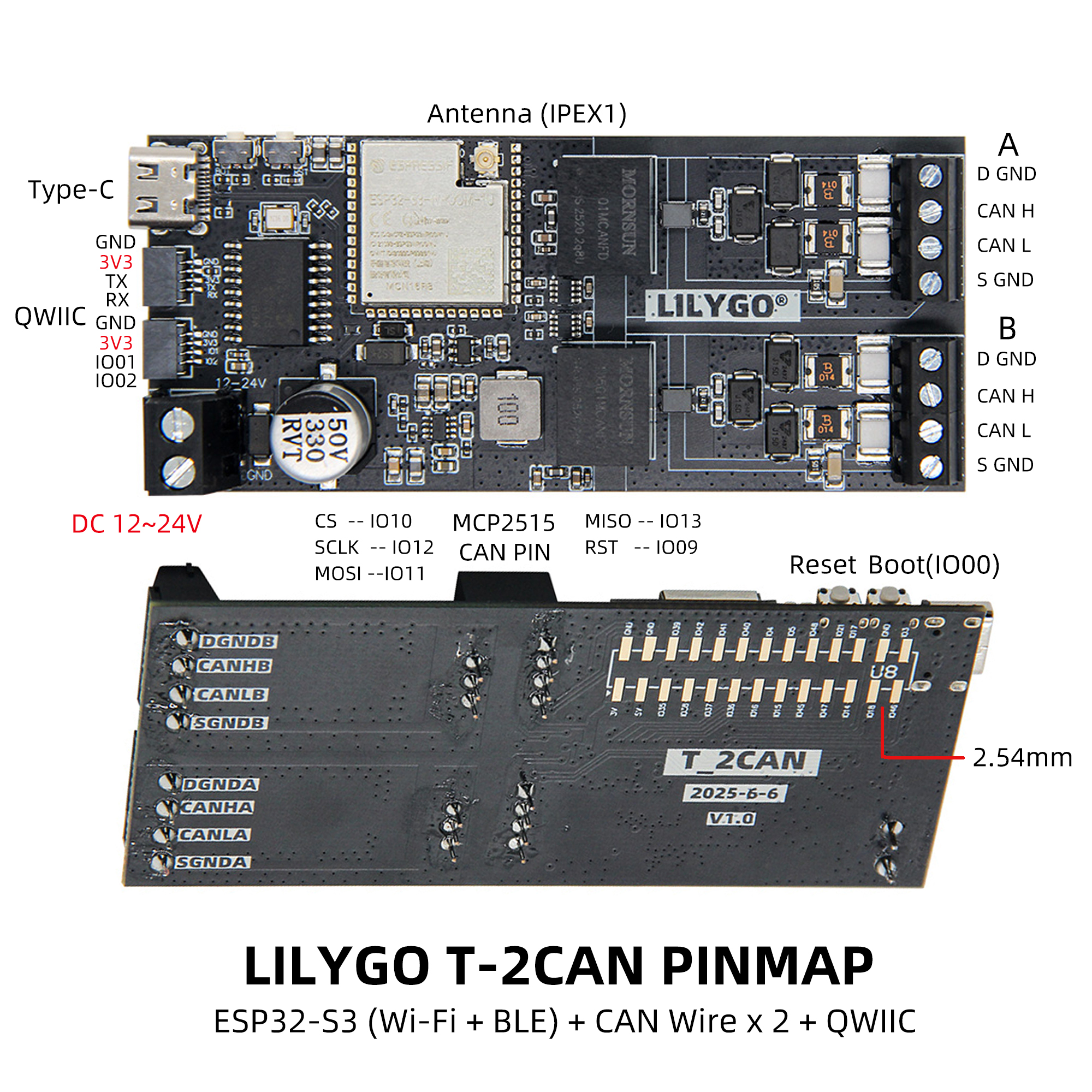
Pin Diagram
Modules
MCU
- Chip: ESP32-S3-WROOM-1U(MCN16R8)
- PSRAM: 8M (OPI PSRAM)
- FLASH: 16M
- Additional Information: More information available at Espressif Official ESP32-S3 Datasheet
CAN Controller
- Chip: MCP2515 × 2
- Protocol Standard: CAN 2.0B
- Communication Rate: Up to 1 Mb/s
- Filters: 6 29-bit acceptance filters + 2 29-bit acceptance masks per channel
- Bus Communication Protocol: SPI
Power Management
- Input Voltage: DC 12-24V
- USB Power Supply: 5V/500mA Type-C interface
- Isolation Design: Signal Ground (SGND) and Power Ground (DGND) separated
Overview
| Component | Description |
|---|---|
| MCU | ESP32-S3-WROOM-1U (MCN16R8) |
| FLASH | 16MB |
| PSRAM | 8MB (OPI PSRAM) |
| CAN Controller | MCP2515 |
| Wireless | 2.4 GHz Wi-Fi & Bluetooth 5 (LE) |
| USB | 1 × USB Port and OTG (TYPE-C) |
| Power Input | 12V~24V DC |
| Expansion Interface | 2 × CAN Interface + 2 × 2.54mm Pitch 13pin Interface + 2 × QWIIC Interface |
| Buttons | 1 × RESET Button + 1 × BOOT Button |
| Antenna | IPEX Antenna Interface |
| Dimensions | 18 × 39 × 91 mm |
Quick Start
Example Support
| Example | [Platformio IDE][espressif32-v6.5.0][Arduino IDE][esp32_v2.0.14] |
Description | Picture |
|---|---|---|---|
| can | Basic CAN communication example | ||
| Original_Test | Factory test program with CAN bus testing |
| Firmware | Description | Picture |
|---|---|---|
| original_test | Factory Program |
PlatformIO
- Install Visual Studio Code, choose the installation according to your system type.
- Open the "Extensions" in the sidebar of Visual Studio Code (or use Ctrl+Shift+X to open extensions), search for the "PlatformIO IDE" extension and install it.
- While the extension is installing, you can go to GitHub to download the program. You can download the main branch program by clicking the green "<> Code" button, or download the "Releases" version from the sidebar.
- After the extension is installed, open the sidebar's Explorer (or use Ctrl+Shift+E to open it), click "Open Folder", find the project code you just downloaded (the entire folder), click "Add", and the project files will be added to your workspace.
- Open the "platformio.ini" file in the project folder (PlatformIO will automatically open the "platformio.ini" of the corresponding folder after successfully adding the folder). Under the "[platformio]" section, uncomment and select the example program you want to upload (marked with "default_envs = xxx"). Then click the "√" at the bottom left to compile. If the compilation is successful, connect the microcontroller to the computer and click the "→" at the bottom left to upload.
Arduino
- Install Arduino IDE, choose the installation according to your system type.
- Open the "example" directory in the project folder, select the example project folder, and open the file ending with ".ino" to open the Arduino IDE project workspace.
- Open the "Tools" menu in the upper right corner -> Select "Board" -> "Board Manager", find or search for "esp32", and download the board files by the author "Espressif Systems". Then return to the "Board" menu and select the development board type under "ESP32 Arduino". The selected development board type should be based on the "board = xxx" header under the [env] directory in the "platformio.ini" file. If there is no corresponding development board, you need to manually add the development board from the "board" directory in the project folder.
- Open the "File" -> "Preferences" menu, find the "Sketchbook location" field, and copy all the library files along with their folders from the "libraries" folder in the project directory to the "libraries" folder in this directory.
- Select the correct settings in the "Tools" menu as shown in the table below.
ESP32-S3
| Setting | Value |
|---|---|
| Board | ESP32S3 Dev Module |
| Upload Speed | 921600 |
| USB Mode | Hardware CDC and JTAG |
| USB CDC On Boot | Enabled |
| USB Firmware MSC On Boot | Disabled |
| USB DFU On Boot | Disabled |
| CPU Frequency | 240MHz (WiFi) |
| Flash Mode | QIO 80MHz |
| Flash Size | 16MB (128Mb) |
| Core Debug Level | None |
| Partition Scheme | 16M Flash (3MB APP/9.9MB FATFS) |
| PSRAM | OPI PSRAM |
| Arduino Runs On | Core 1 |
| Events Run On | Core 1 |
- Select the correct port.
- Click the "√" in the upper right corner to compile. If the compilation is successful, connect the microcontroller to the computer and click the "→" in the upper right corner to upload.
Development Platforms
FAQ
Q. I still don't know how to set up the programming environment after reading the above tutorial. What should I do?
A. If you still don't understand how to set up the environment after reading the above tutorial, you can refer to the LilyGo-Document documentation for setup instructions.Q. Why does Arduino IDE prompt me to update library files when I open it? Should I update or not?
A. Choose not to update library files. Different versions of library files may not be compatible with each other, so it is not recommended to update library files.Q. Why is there no serial data output from the "Uart" interface on my board? Is it broken and unusable?
A. Because the project file is configured by default to use the USB interface as Uart0 serial output for debugging, the "Uart" interface is connected to Uart0 and will not output any data without configuration.
PlatformIO users please open the project file "platformio.ini", modify the option "-DARDUINO_USB_CDC_ON_BOOT=true" under "build_flags = xxx" to "-DARDUINO_USB_CDC_ON_BOOT=false" to normally use the external "Uart" interface.
Arduino users open the "Tools" menu, select USB CDC On Boot: "Disabled" to normally use the external "Uart" interface.Q. Why does my board keep failing to upload programs?
A. Please hold down the "BOOT" button and try uploading the program again.