


 English
LILYGO T-Deck Pro
Version History:
Different hardware versions may have incompatible code. Please confirm your hardware version and enter the corresponding git branch.
Hardware differences can be viewed in the corresponding "readme" files and "schematic diagrams".
| Name | Git Branch | Change | Schematic | Firmware | State |
|---|---|---|---|---|---|
| T-Deck-Pro V1.0 | HD-V1-250326 | readme | SCH | V1 | Available |
| T-Deck-Pro V1.1 | HD-V2-250915 | readme | SCH | V2 | Available |
| T-Deck-Pro MAX V1.0 | HD-V3-250911 | readme | SCH | V3 | Not Available |
Purchase Links
| Product | SOC | FLASH | PSRAM | Link |
|---|---|---|---|---|
| T-Deck Pro | ESP32-S3FN16R8 | 16MB | 8MB | LILYGO Mall |
Table of Contents
- Description
- Preview
- Modules
- Quick Start
- Pin Overview
- Related Tests
- FAQ
- Projects
- Resources
- Dependent Libraries
Description
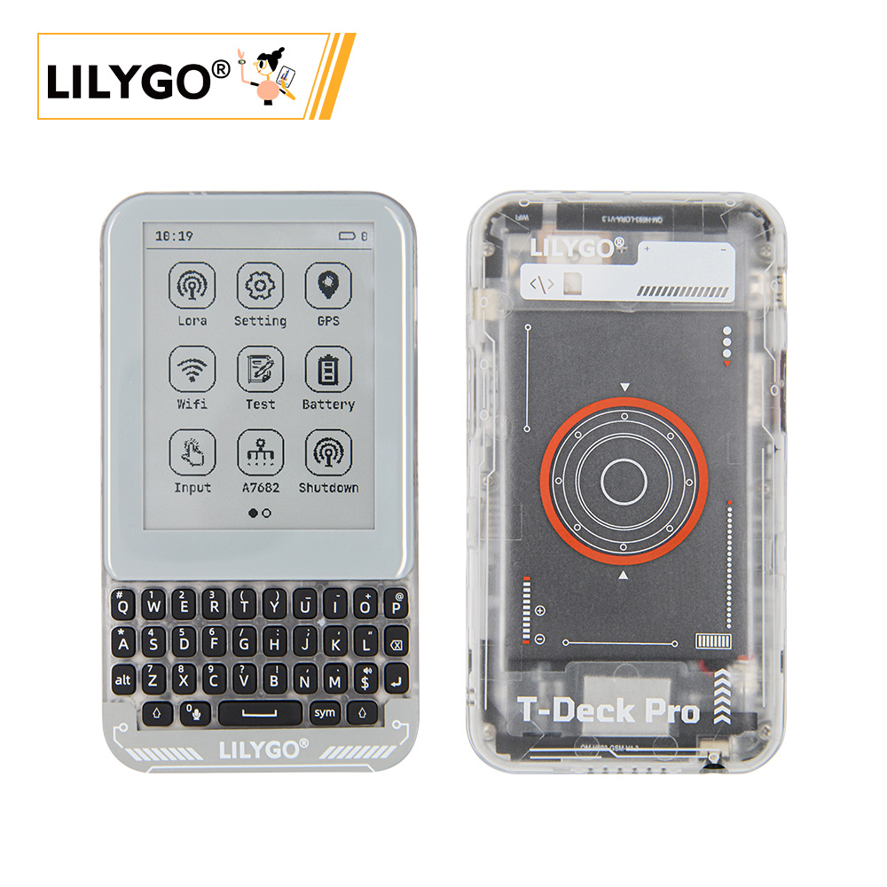
LILYGO T-Deck Pro is a highly integrated multi-functional development platform based on the ESP32-S3 chip, supporting 4G communication and LoRa long-distance wireless transmission, equipped with an electronic ink screen (EPD) and touch function, balancing low-power display and interaction. Its hardware modules include GPS positioning, gyroscope sensing, microphone voice input, SD card storage, mechanical keyboard, and self-learning AI IMU, suitable for IoT, outdoor equipment, smart terminals, and other scenarios. You can choose the desired version according to your needs (Version 1 is equipped with audio module PCM512A, Version 2 is equipped with 4G module A7682E), providing flexible configuration to meet diverse needs such as industrial control, environmental monitoring, and portable devices.
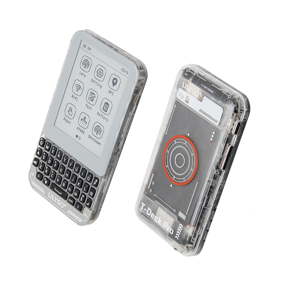
Preview
Physical Image
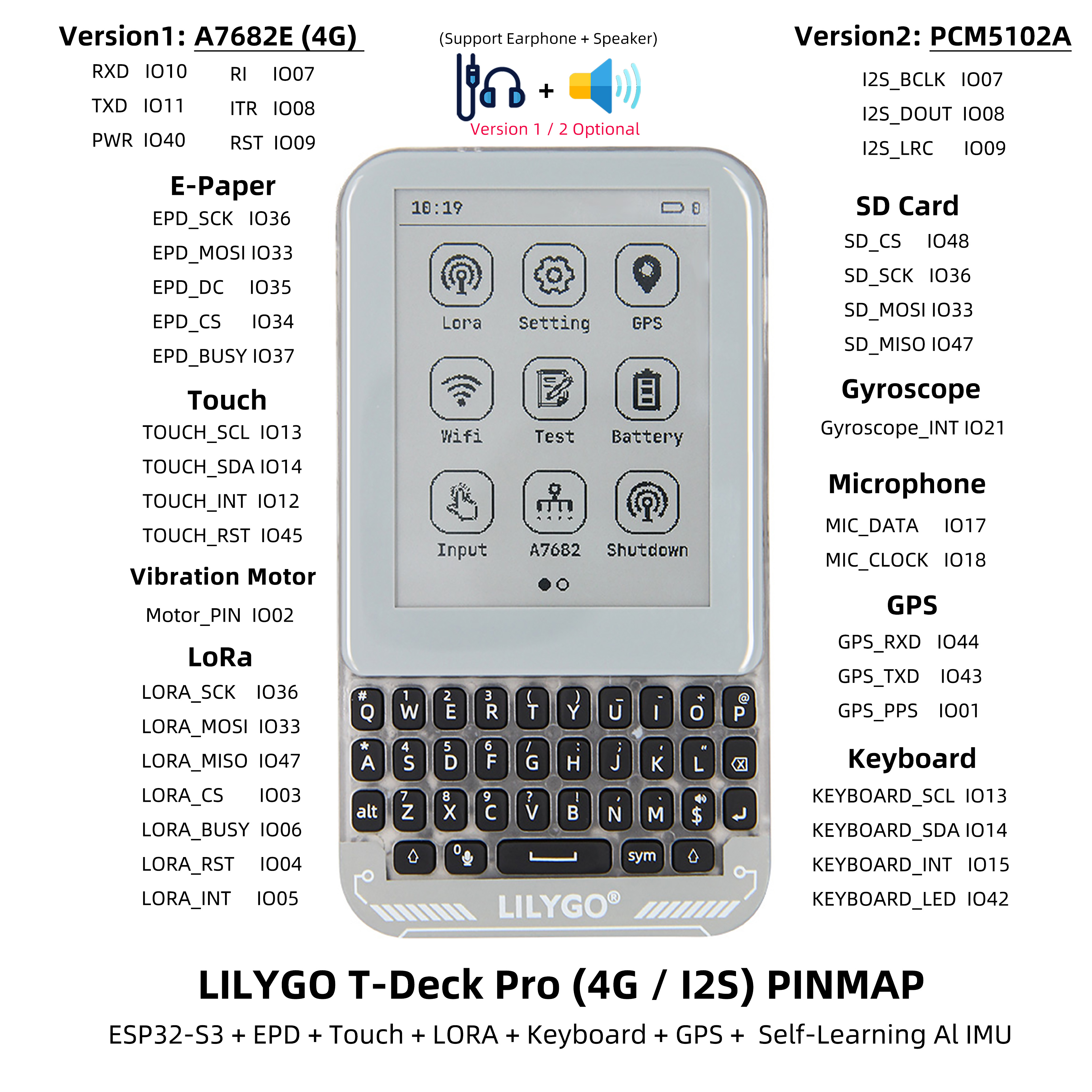
Pinout Diagram
Modules
MCU
- Chip: ESP32-S3FN16R8 Dual-core LX7 microprocessor
- PSRAM: 8MB
- FLASH: 16MB
- Wireless: Wi-Fi 802.11 b/g/n; Bluetooth 5.0 (LE)
- Other Notes: For more information, please visit Espressif Official ESP32-S3 Datasheet
Communication Modules
- 4G Module: A7682E (optional version)
- LoRa: SX1262 chip, supports 433MHz~920MHz frequency bands
- GPS: MIA-M10Q GNSS module
- SIM Card: Supports mobile communication
Display and Input
- Screen: GDEQ031T10 3.1-inch electronic ink display
- Resolution: 320×240 pixels
- Touch: CST328 touch controller
- Keyboard: TCA8418 mechanical keyboard controller
Sensor System
- Gyroscope: BHI260AP AI IMU sensor
- Light Sensor: LTR_553ALS ambient light sensor
- Microphone: Supports voice input
Audio System
- Audio Module: PCM512A (optional version)
- Function: High-quality audio output
Power Management
- Battery: 3.7V 1500mAh lithium polymer battery
- Charging Chip: BQ25896/BQ27220
- USB Power: 5V/500mA Type-C interface
Overview
| Component | Description |
|---|---|
| MCU | ESP32-S3FN16R8 Dual-core LX7 microprocessor |
| FLASH | 16MB |
| PSRAM | 8MB |
| 4G Module | A7682E (Optional) |
| LoRa | SX1262 (433MHz~920MHz) |
| GPS | MIA-M10Q GNSS module |
| Screen | GDEQ031T10 3.1-inch E-Paper Display (320×240) |
| Touch | CST328 Touch Controller |
| Keyboard | TCA8418 Mechanical Keyboard |
| Gyroscope | BHI260AP AI IMU Sensor |
| Audio | PCM512A (Optional) |
| Light Sensor | LTR_553ALS Ambient Light Sensor |
| Battery | 3.7V 1500mAh Lithium Polymer Battery |
| Battery Management | BQ25896/BQ27220 Charging Chip |
| Storage | TF Card Expansion |
| Wireless | 2.4 GHz Wi-Fi & Bluetooth 5 (LE) |
| Communication | SIM Card Support |
| USB | 1 × USB Port and OTG (TYPE-C Interface) |
| IO Interface | 2.54mm pitch 2×20 dual-row expansion IO interface |
| Expansion Interface | 1 × QWIIC Interface |
| Motor Control | IO Level Control |
| Buttons | 1 x RESET Button + 1 x BOOT Button |
| Power | 5V/500mA |
| Mounting Holes | 2 × 2mm mounting holes |
| Dimensions | 120×66×13.5mm |
A7682E
Test the functionality of the A7682E using examples/A7682E/test_AT
A7682E is the LTE Cat 1 module that supports wireless communication modes of LTE-FDD/GSM/GPRS/EDGE. It supports maximum 10Mbps downlink rate and 5Mbps uplink rate. A7682E supports multiple built-in network protocols.
Control Via AT Commands
Frequency Bands LTE-FDD B1/B3/B5/B7/B8/B20
GSM/GPRS/EDGE 900/1800 MHz
Supply Voltage 3.4V ~ 4.2V, Typ: 3.8V
LTE Cat 1   (Uplink up to 5Mbps, Downlink up to10Mbps)
EDGE        (Uplink/Downlink up to 236.8Kbps)
GPRS        (Uplink/Downlink up to 85.6Kbps)
Firmware update via USB/FOTA
Support language calls
Support sending and receiving SMS messages
Network protocols (TCP/IP/IPV4/IPV6/Multi-PDP/FTP/FTPS/HTTP/HTTPS/DNS)
RNDIS/PPP/ECM
SSL
Quick Start
Example Support
├─boards  : Some information about the board for the platformio.ini configuration project;
├─docs    : Place some documents;
├─data    : Picture resources used by the program;
├─example : Some examples;
├─firmare : `factory` compiled firmware;
├─hardware: Schematic diagram of the board, chip data;
└─lib     : Libraries used in the project;
PlatformIO
- Install Visual Studio Code and Python, then clone or download this project;
- Search for the
PlatformIOplugin inVisualStudioCodeextensions and install it; - After installation, you need to restart "Visual Studio Code".
- After opening this project, PlatformIO will automatically download the required third-party libraries and dependencies. The first download process is relatively long, please be patient;
- After installing all dependencies, you can open the
platformio.iniconfiguration file, uncomment inexampleto select a routine, then pressctrl+sto save the.iniconfiguration file; - In VScode, click :ballot_box_with_check: to compile the project, then insert USB and select COM in VScode.
- Finally, click :arrow_right: to download the program to Flash;
Arduino
- Install Arduino IDE, choose the version for your system.
- Open the "example" directory in the project folder, select the example project folder, and open the file ending with ".ino" to open the Arduino IDE project workspace.
- Open the "Tools" menu in the top bar -> Select "Board" -> "Boards Manager", find or search for "esp32", and install the board files by "Espressif Systems". Then return to the "Board" menu and select the board type under "ESP32 Arduino".
- Open the menu bar "File" -> "Preferences", find the "Sketchbook location" field, and copy all the library files along with their folders from the "libraries" folder in the project directory to the "libraries" folder in this location.
- Select the correct settings in the "Tools" menu as shown in the table below.
ESP32-S3
| Setting | Value |
|---|---|
| Board | ESP32S3 Dev Module |
| Upload Speed | 921600 |
| USB Mode | Hardware CDC and JTAG |
| USB CDC On Boot | Enabled |
| USB Firmware MSC On Boot | Disabled |
| USB DFU On Boot | Disabled |
| CPU Frequency | 240MHz (WiFi) |
| Flash Mode | QIO 80MHz |
| Flash Size | 16MB (128Mb) |
| Core Debug Level | None |
| Partition Scheme | 16M Flash (3MB APP/9.9MB FATFS) |
| PSRAM | OPI PSRAM |
| Arduino Runs On | Core 1 |
| Events Run On | Core 1 |
- Select the correct port.
- Click the "√" in the top right corner to compile. If the compilation is successful, connect the microcontroller to your computer and click "→" in the top right corner to upload.
Development Platforms
Pin Overview
// Serial
#define SerialMon   Serial      //
#define SerialAT    Serial1     //
#define SerialGPS   Serial2     //

// IIC Addr
#define BOARD_I2C_ADDR_TOUCH      0x1A // Touch        --- CST328
#define BOARD_I2C_ADDR_LTR_553ALS 0x23 // Light sensor --- LTR_553ALS
#define BOARD_I2C_ADDR_GYROSCOPDE 0x28 // Gyroscope    --- BHI260AP
#define BOARD_I2C_ADDR_KEYBOARD   0x34 // Keyboard     --- TCA8418
#define BOARD_I2C_ADDR_BQ27220    0x55 // BQ27220
#define BOARD_I2C_ADDR_BQ25896    0x6B // BQ25896

// IIC
#define BOARD_I2C_SDA  13
#define BOARD_I2C_SCL  14

// Keyboard
#define BOARD_KEYBOARD_SCL BOARD_I2C_SCL
#define BOARD_KEYBOARD_SDA BOARD_I2C_SDA
#define BOARD_KEYBOARD_INT 15
#define BOARD_KEYBOARD_LED 42

// Touch
#define BOARD_TOUCH_SCL BOARD_I2C_SCL
#define BOARD_TOUCH_SDA BOARD_I2C_SDA
#define BOARD_TOUCH_INT 12
#define BOARD_TOUCH_RST 45

// LTR-553ALS-WA  beam sensor
#define BOARD_ALS_SCL BOARD_I2C_SCL
#define BOARD_ALS_SDA BOARD_I2C_SDA
#define BOARD_ALS_INT 16

// Gyroscope
#define BOARD_GYROSCOPDE_SCL BOARD_I2C_SCL
#define BOARD_GYROSCOPDE_SDA BOARD_I2C_SDA
#define BOARD_GYROSCOPDE_INT 21
#define BOARD_GYROSCOPDE_RST -1

// SPI
#define BOARD_SPI_SCK  36
#define BOARD_SPI_MOSI 33
#define BOARD_SPI_MISO 47

// Display
#define LCD_HOR_SIZE 240
#define LCD_VER_SIZE 320
#define DISP_BUF_SIZE (LCD_HOR_SIZE * LCD_VER_SIZE)

#define BOARD_EPD_SCK  BOARD_SPI_SCK
#define BOARD_EPD_MOSI BOARD_SPI_MOSI
#define BOARD_EPD_DC   35
#define BOARD_EPD_CS   34
#define BOARD_EPD_BUSY 37
#define BOARD_EPD_RST  -1

// SD card
#define BOARD_SD_CS   48
#define BOARD_SD_SCK  BOARD_SPI_SCK
#define BOARD_SD_MOSI BOARD_SPI_MOSI
#define BOARD_SD_MISO BOARD_SPI_MISO

// Lora
#define BOARD_LORA_SCK  BOARD_SPI_SCK
#define BOARD_LORA_MOSI BOARD_SPI_MOSI
#define BOARD_LORA_MISO BOARD_SPI_MISO
#define BOARD_LORA_CS   3
#define BOARD_LORA_BUSY 6
#define BOARD_LORA_RST  4
#define BOARD_LORA_INT  5

// GPS
#define BOARD_GPS_RXD 44
#define BOARD_GPS_TXD 43
#define BOARD_GPS_PPS 1

// A7682E Modem
#define BOARD_A7682E_RI     7
#define BOARD_A7682E_ITR    8
#define BOARD_A7682E_RST    9
#define BOARD_A7682E_RXD    10
#define BOARD_A7682E_TXD    11
#define BOARD_A7682E_PWRKEY 40

// PCM5102A
#define BOARD_I2S_BCLK 7
#define BOARD_I2S_DOUT 8
#define BOARD_I2S_LRC 9

// Boot pin
#define BOARD_BOOT_PIN  0

// Motor pin
#define BOARD_MOTOR_PIN 2

// EN
#define BOARD_GPS_EN  39  // enable GPS module
#define BOARD_1V8_EN  38  // enable gyroscope module
#define BOARD_6609_EN 41  // enable 7682 module
#define BOARD_LORA_EN 46  // enable LORA module

// Mic
#define BOARD_MIC_DATA        17
#define BOARD_MIC_CLOCK       18
// -------------------------------------------------
Related Tests
Screen Refresh Methods
Refresh process explanation: (Refresh time: the entire process from when the screen has action to when the image stabilizes)
| Refresh Type | Visual Performance | Usage Recommendation |
|---|---|---|
| Full Refresh | Accompanied by multiple flashes | Basic refresh mode |
| Fast Refresh | Flashes once | Requires full refresh after ≤5 consecutive operations |
| Partial Refresh | No flashing | Requires full refresh after ≤5 consecutive operations |
Note: After 5 consecutive operations of fast refresh and partial refresh, a full refresh must be performed to eliminate ghosting accumulation.
FAQ
Q. I still don't know how to set up the programming environment after reading the above tutorial. What should I do?
A. If you still don't understand how to set up the environment after reading the above tutorial, you can refer to the LilyGo-Document documentation for setup instructions.Q. Why does Arduino IDE prompt me to upgrade library files when I open it? Should I upgrade or not?
A. Choose not to upgrade library files, as different versions of library files may not be compatible with each other, so upgrading is not recommended.Q. What should I do if ghosting appears on the e-paper display?
A. After 5 consecutive uses of fast refresh or partial refresh, a full refresh must be performed to eliminate ghosting.Q. Why does my board keep failing to program?
A. Please hold the "BOOT" button and try downloading the program again.
Projects
Resources
- ESP32-S3 Datasheet
- MAX98357A Audio Amplifier
- MSM261S4030H0R Microphone
- PCF85063ATL RTC
- MP34DT05-A Microphone
Dependent Libraries
zinggjm/GxEPD2@1.5.5
jgromes/RadioLib@6.4.2
lewisxhe/SensorLib@^0.2.0
mikalhart/TinyGPSPlus @ ^1.0.3
vshymanskyy/TinyGSM@^0.12.0
lvgl/lvgl @ ~8.3.9
lewisxhe/XPowersLib @ ^0.2.4
adafruit/Adafruit TCA8418 @ ^1.0.1
adafruit/Adafruit BusIO @ ^1.14.4
olikraus/U8g2_for_Adafruit_GFX@^1.8.0
adafruit/Adafruit GFX Library@^1.11.10
esphome/ESP32-audioI2S#v3.0.12