


 English
LILYGO T3-STM32
Purchase Links
| Product | SOC | FLASH | SRAM | Link |
|---|---|---|---|---|
| T3-STM32 | STM32WL55CCU6 | 256KB | 64KB | LILYGO Store |
Table of Contents
- Description
- Preview
- Modules
- Quick Start
- Pin Overview
- Related Tests
- FAQ
- Projects
- Resources
- Dependent Libraries
Description
LILYGO T3 STM32 is a versatile IoT development board based on the STM32WL55CCU6 low-power microcontroller, integrating LoRa long-range communication module that supports 433/868/915MHz multi-band, adapting to global IoT application scenarios. Its hardware configuration includes 256KB flash and 64KB SRAM, equipped with an SSD1315-driven OLED display (controlled via I2C interface), TF card storage expansion (SPI protocol), and solar input interface (4.4~6V), supporting outdoor energy harvesting and low-power operation. The onboard rich GPIO pins are compatible with various peripheral interfaces such as SPI, I2C, timers, and reserved QWIIC ecosystem connectors for easy sensor expansion. Suitable for rapid development of IoT terminals such as remote monitoring, environmental sensing, LoRa gateways, and solar-powered devices.
Preview
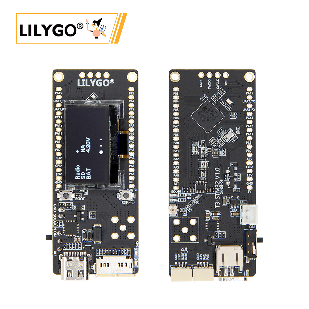
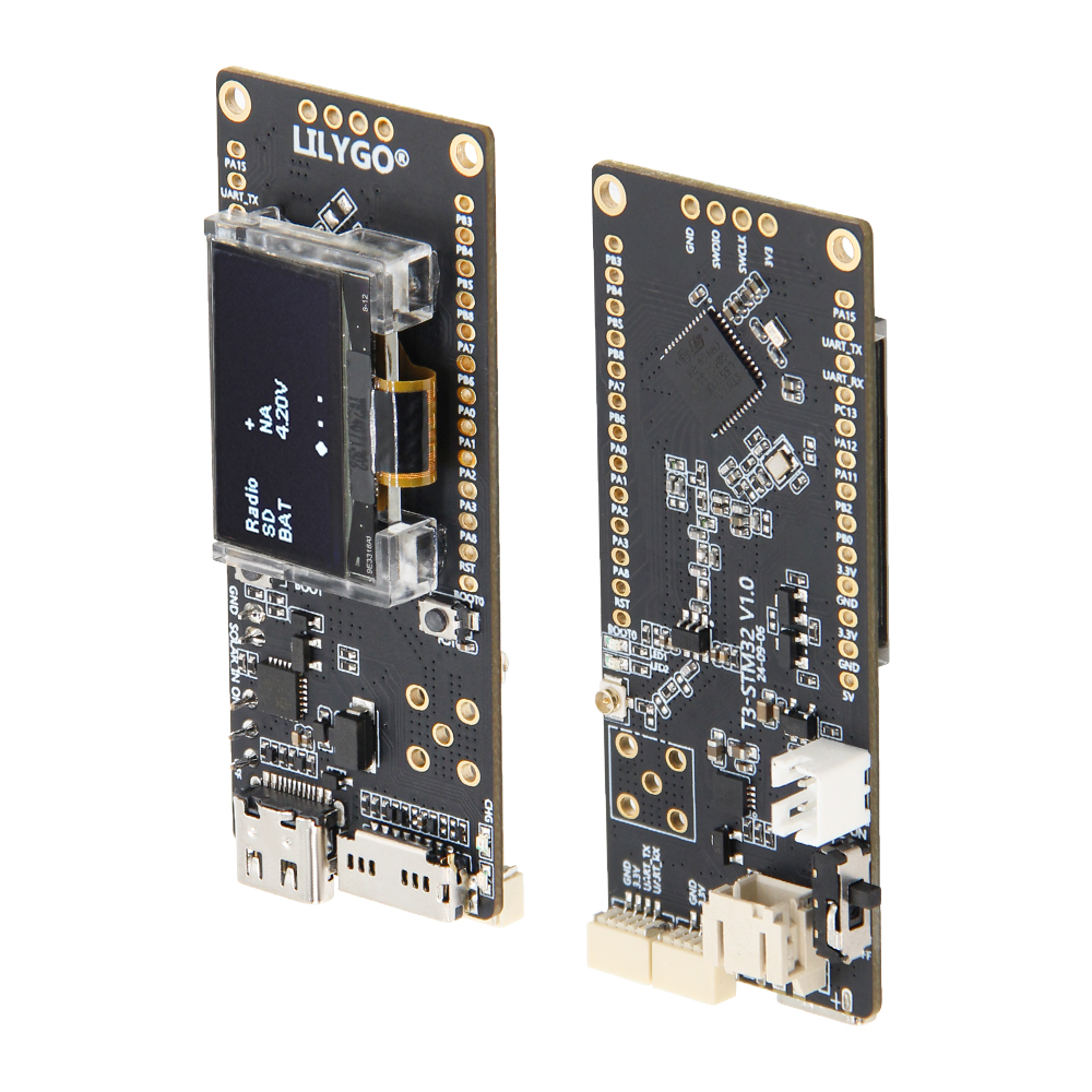
Physical Image
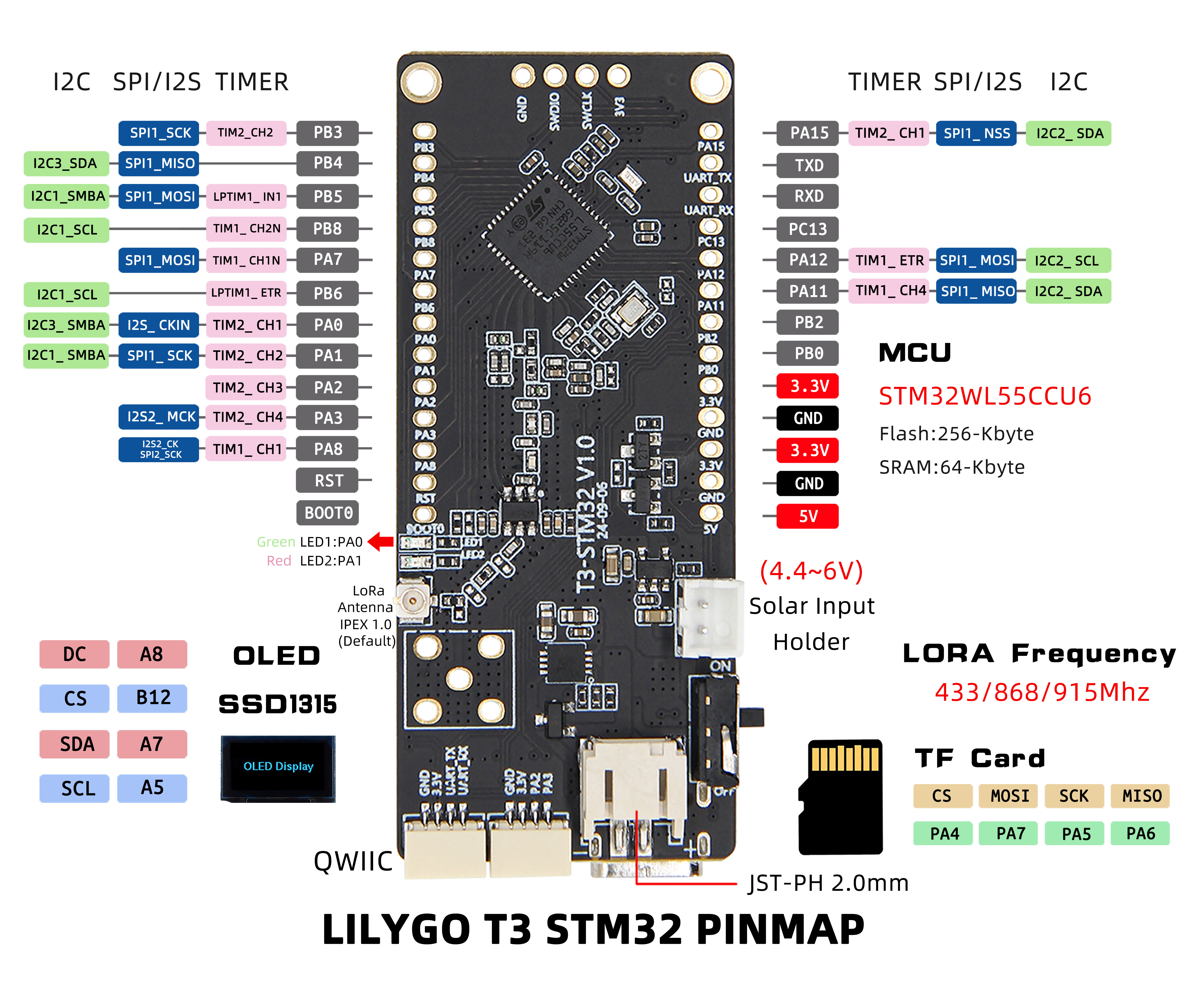
Pin Diagram
Modules
MCU
- Chip: STM32WL55CCU6
- Architecture: 32-bit Arm® Cortex®-M4 + Cortex®-M0+ Dual-core
- FLASH: 256KB
- SRAM: 64KB
- Built-in Radio: LoRa®, (G)FSK, (G)MSK, BPSK
Display
- Size: 0.96-inch OLED display
- Resolution: 128×64px
- Driver Chip: SSD1315
- Interface: I2C
Wireless Communication
- LoRa: SX1262
- Frequency Band: 433MHz/868MHz/915MHz (selectable)
- Antenna Interface: Standard SMA interface
Power Management
- Power Supply: USB Type-C
- Solar Input: 4.4~6V
- Battery Switch: Supports battery power switching
Overview
| Component | Description |
|---|---|
| MCU | STM32WL55CCU6 Dual-core Cortex-M4+M0+ |
| FLASH | 256KB |
| SRAM | 64KB |
| Display | 0.96-inch SSD1315 OLED (128×64) |
| LoRa | SX1262 (433/868/915MHz) |
| Built-in Radio | LoRa®, (G)FSK, (G)MSK, BPSK |
| Storage | TF Card Expansion (SPI) |
| USB | 1 × USB Port (TYPE-C) |
| Expansion Interface | 2 × QWIIC Interface + 2.54mm Pitch 2×13 GPIO |
| Debug Interface | 2.54mm Pitch 4-pin SWD Interface |
| Power Interface | Solar Input Interface (4.4~6V) |
| Antenna Interface | LoRa Antenna Interface + 5-pin Antenna Socket |
| Buttons | 1 x RESET Button + 1 x BOOT Button |
| Mounting Holes | 2 × 2mm Positioning Holes |
| Dimensions | 66 × 27 × 13 mm |
Quick Start
Development Tools Preparation
Download Tools
- STM32CubeProgrammer - ST Official Download
- J-Link - SEGGER Download
- ST-Link - ST Official Driver
Note: JLink, STLink, and STM32CubeProgrammer all require drivers to function properly
Development Platforms
Example Support
├─1_led : Create simple projects
├─2_jlink_rtt_print : Used only to test jlink printing
├─3_sdcard : Test TF card screen
├─4_oled : Test oled screen
├─5_RF_test : This example is AT Slave and is only used for RF testing
├─6_SubGHz_TXRX : Transceiver test using Lora modulation
├─DeepSleep : Test board sleep power consumption
├─PingPong : Port CubeMX package SubGHz_Phy_PingPong program
Related Tests
FAQ
Q. Which debuggers are supported?
A. Supports various debuggers like ST-Link, J-Link, connected via 4-pin SWD interface.Q. What are the requirements for solar input?
A. Supports 4.4~6V solar input, suitable for outdoor energy harvesting applications.Q. How to select LoRa frequency band?
A. Provides three frequency band versions: 433MHz, 868MHz, 915MHz. Please select according to regional regulatory requirements.