


 English
LILYGO T-Deck
Version History:
| Version | Update Date | Update Description |
|---|---|---|
- T-Deck-Plus has allocated the pins on the Grove interface for GPS module use, so the Grove interface on T-Deck-Plus cannot be used
- T-Deck updated the TFT_eSPI ST7789 initialization sequence on 20240726. Currently, this change has not been pushed to the TFT_eSPI upstream branch. If you encounter incorrect screen display during use, please check if this matches the initialization sequence in the repository.
Purchase Links
| Product | SOC | FLASH | PSRAM | Link |
|---|---|---|---|---|
| T-Deck | ESP32-S3FN16R8 | 16MB | 8MB | LILYGO Mall |
Table of Contents
- Description
- Preview
- Modules
- Quick Start
- Pin Overview
- Related Tests
- FAQ
- Projects
- Resources
- Dependent Libraries
Description
LILYGO T-Deck is a highly integrated multi-functional embedded development platform based on the ESP32-S3 main control chip, integrating a 2.8-inch 320x240 resolution ST7789 display, trackball navigation module (with directional keys and BOOT button), physical keyboard interface (via I²C communication), TF card storage expansion, LoRa wireless communication module (supporting SCK/MISO/MOSI and control pins), and ES7210 microphone array (for audio input). Its pin layout accommodates display driving (DC/BL/SPI), touch control, sensor interaction (SDA/SCL/INT), power management (BAT ADC), and modular expansion (SPI/I²C/UART), enabling rapid development of IoT terminals, portable interactive devices, or low-power wireless communication projects.
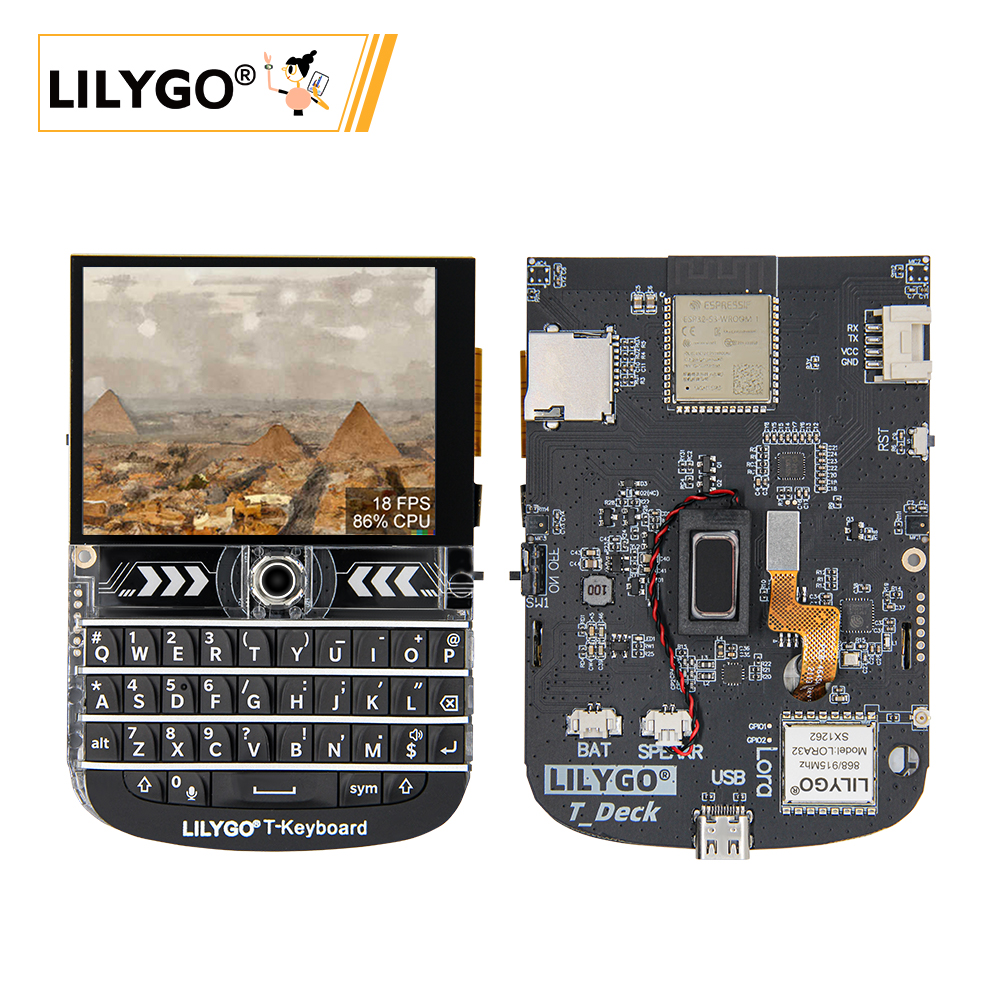
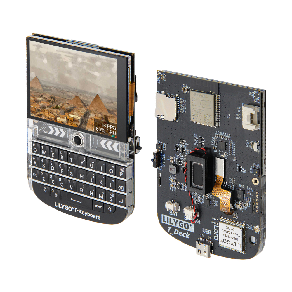
Preview
Physical Image
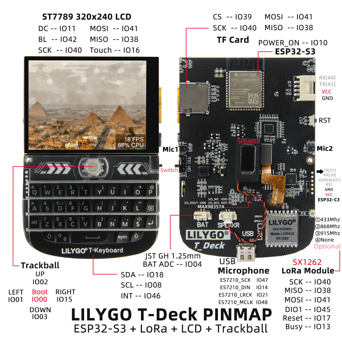
Pinout Diagram
Modules
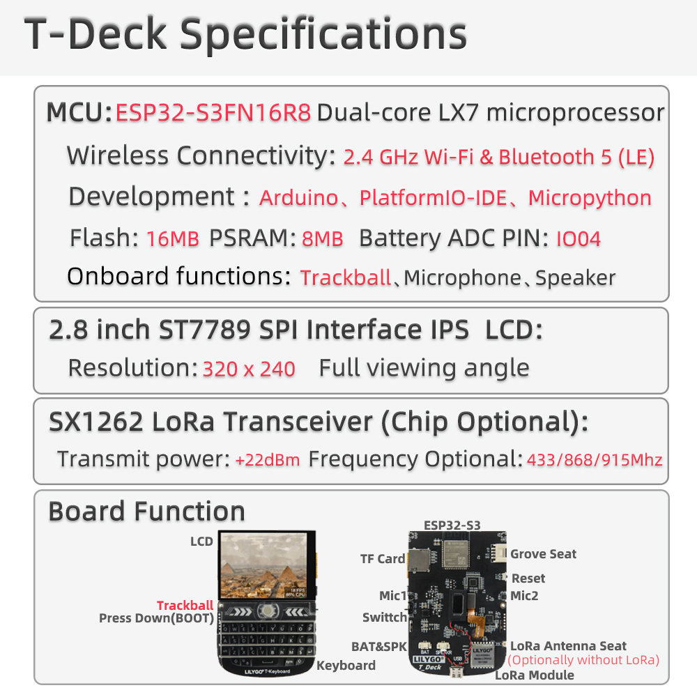
MCU
- Chip: ESP32-S3FN16R8 Dual-core LX7 microprocessor
- PSRAM: 8MB
- FLASH: 16MB
- Wireless: Wi-Fi 802.11 b/g/n; Bluetooth 5.0 (LE)
- Other Notes: For more information, please visit Espressif Official ESP32-S3 Datasheet
Communication Modules
- LoRa: SX1262 chip, supports 433MHz~915MHz frequency bands (optional)
- GPS: MIA-M10Q GNSS module
- Wireless: 2.4GHz Wi-Fi & Bluetooth 5.0 (LE)
Display and Input
- Screen: 2.8-inch ST7789 LCD
- Resolution: 320×240 pixels
- Control Method: Trackball navigation module (replaces touch screen)
- Keyboard: Physical keyboard interface (I²C communication)
Audio System
- Microphone: MSM381A3729H9CP microphone array
- Audio Chip: ES7210 audio codec
Power Management
- Battery: 2000mAh lithium polymer battery
- Switch: Supports power switch
- USB Power: Type-C interface
Overview
The T-Deck version does not have a touch screen, using a trackball navigation module instead.
| Component | Description |
|---|---|
| MCU | ESP32-S3FN16R8 Dual-core LX7 microprocessor |
| FLASH | 16MB |
| PSRAM | 8MB |
| LoRa | SX1262 (433MHz~915MHz optional) |
| GPS | MIA-M10Q GNSS module |
| Screen | 2.8-inch ST7789 LCD (320×240) |
| Control Method | Trackball navigation module |
| Input | Physical keyboard (I²C interface) |
| Audio | ES7210 audio codec |
| Microphone | MSM381A3729H9CP microphone array |
| Battery | 2000mAh lithium polymer battery |
| Storage | TF card expansion |
| Wireless | 2.4 GHz Wi-Fi & Bluetooth 5 (LE) |
| USB | 1 × Type-C interface |
| IO Expansion | 2mm pitch 6-pin expansion interface |
| Expansion Interface | GPS expansion interface + 2 × JST GH 1.25mm + 1 × 4-pin expansion interface |
| Buttons | 1 x RST button + 1 x BOOT button (trackball) |
| Switch | Power switch |
| Mounting Holes | 2mm mounting holes |
| Dimensions | 10×6.8×1.1 cm |
Quick Start
Example Support
├─Keyboard_ESP32C3       # ESP32C3 keyboard I2C slave
├─Keyboard_T_Deck_Master # T-Deck read from keyboard
├─Microphone             # Noise detection
├─Touchpad               # Read touch coordinates
├─GPSShield              # GPS Shield example
└─UnitTest               # Factory hardware unit testing
- If microphone is enabled, then the middle button on the board, GPIO0, is not available.
- If you encounter issues uploading sketches, you need to press the trackball middle button, then insert USB. This puts the chip in download mode, then click upload sketch.
- The ESP32C3 programming interface is on the 6-pin header on the RST button side. Starting from above the RST button, the order is: 3V3, GND, RST, BOOT, RX, TX.
PlatformIO
- Install VisualStudioCode and Python
- Search for the
PlatformIOplugin inVisualStudioCodeextensions and install it. - After installation, you need to restart
VisualStudioCode - After restarting
VisualStudioCode, selectFile->Open Folder-> select theT-Deckdirectory - Click on the
platformio.inifile, in theplatformiosection, uncomment the example line you want to use, ensuring only one line is active - Click the (✔) symbol at the bottom left to compile
- Connect the board to computer USB
- Click (→) to upload firmware
- Click (plug symbol) to monitor serial output
ArduinoIDE
- Install ArduinoIDE
- Copy all folders from the
T-Deck/libdirectory to<C:\Users\UserName\Documents\Arduino\libraries>. If there is nolibrariesdirectory, please create one. Note: do not copy thelibdirectory itself, but the folders inside the lib directory. - Open ArduinoIDE -> Tools
- Board -> ESP32S3 Dev Module
- USB CDC On Boot -> Enable # Note: when not connected to USB, you need to change Enable to Disable so USB CDC does not block board startup
- CPU Frequency -> 240MHz
- USB DFU On Boot -> Disable
- Flash Mode -> QIO 80MHz
- Flash Size -> 16MB(128Mb)
- USB Firmware MSC On Boot -> Disable
- PSRAM -> OPI PSRAM
- Partition Scheme -> 16M Flash(3MB APP/9.9MB FATFS)
- USB Mode -> Hardware CDC and JTAG
- Upload Mode -> UART0/Hardware CDC
- Upload Speed -> 921600
- Insert USB to PC, click Upload <If unable to upload successfully, keep pressing BOOT button, then click RST, then click Upload. After upload completes, click RST to exit download mode>
Development Platforms
Pin Overview
    //! The board peripheral power control pin needs to be set to HIGH when using the peripheral
    #define BOARD_POWERON       10

    #define BOARD_I2S_WS        5
    #define BOARD_I2S_BCK       7
    #define BOARD_I2S_DOUT      6

    #define BOARD_I2C_SDA       18
    #define BOARD_I2C_SCL       8

    #define BOARD_BAT_ADC       4

    #define BOARD_TOUCH_INT     16
    #define BOARD_KEYBOARD_INT  46

    #define BOARD_SDCARD_CS     39
    #define BOARD_TFT_CS        12
    #define RADIO_CS_PIN        9

    #define BOARD_TFT_DC        11
    #define BOARD_TFT_BACKLIGHT 42

    #define BOARD_SPI_MOSI      41
    #define BOARD_SPI_MISO      38
    #define BOARD_SPI_SCK       40

    #define BOARD_TBOX_G02      2
    #define BOARD_TBOX_G01      3
    #define BOARD_TBOX_G04      1
    #define BOARD_TBOX_G03      15

    #define BOARD_ES7210_MCLK   48
    #define BOARD_ES7210_LRCK   21
    #define BOARD_ES7210_SCK    47
    #define BOARD_ES7210_DIN    14

    #define RADIO_BUSY_PIN      13
    #define RADIO_RST_PIN       17
    #define RADIO_DIO1_PIN      45

    #define BOARD_BOOT_PIN      0

    #define BOARD_BL_PIN        42


    #define BOARD_GPS_TX_PIN                 43
    #define BOARD_GPS_RX_PIN                 44


    #ifndef RADIO_FREQ
    #ifdef  JAPAN_MIC
    #define RADIO_FREQ           920.0
    #else
    #define RADIO_FREQ           868.0
    #endif
    #endif

    #ifndef RADIO_BANDWIDTH
    #define RADIO_BANDWIDTH      125.0
    #endif

    #ifndef RADIO_SF
    #define RADIO_SF             10
    #endif

    #ifndef RADIO_CR
    #define RADIO_CR             6
    #endif

    #ifndef RADIO_TX_POWER
    #define RADIO_TX_POWER       22
    #endif

    #define DEFAULT_OPA          100
Related Tests
FAQ
Q. I still don't know how to set up the programming environment after reading the above tutorial. What should I do?
A. If you still don't understand how to set up the environment after reading the above tutorial, you can refer to the LilyGo-Document documentation for setup instructions.Q. Why does Arduino IDE prompt me to upgrade library files when I open it? Should I upgrade or not?
A. Choose not to upgrade library files, as different versions of library files may not be compatible with each other, so upgrading is not recommended.Q. Does T-Deck have touch screen functionality?
A. The T-Deck version does not have a touch screen, using a trackball navigation module instead of touch operation.Q. Why does my board keep failing to program?
A. Please hold the "BOOT" button and try downloading the program again.