


 English
LILYGO T-Connect Pro
Version History:
| Version | Update date | Update description |
|---|---|---|
| T-Connect-Pro_V1.0 | Initial Version |
Purchase Links
| Product | SOC | FLASH | PSRAM | Link |
|---|---|---|---|---|
| T-Connect Pro | ESP32-S3-R8 | 16MB | 8MB | LILYGO Mall |
Table of Contents
Description
T-Connect-Pro is a multi-functional industrial-grade control and communication module based on ESP32-S3, integrating LoRa (SX1262 chip), ST7796 LCD display, CAN bus, Ethernet interface, and dual serial ports (RS232/RS485), supporting 12~24V wide voltage input and 10A relay output, suitable for complex industrial automation and IoT scenarios.
Core Features
- Multi-protocol Communication: Integrates LoRa long-distance transmission, CAN bus control, Ethernet, RS232/RS485 serial ports
- Industrial-grade Design: Supports 12~24V wide voltage input, 10A relay output
- Rich Interfaces: 3-layer board stacking design, integrated touch screen, sensors, QWIIC expansion interface
- Real-time Display: ST7796 TFT screen provides intuitive data display and operation interface
- Power Management: AXP2101 highly integrated power management unit
Preview
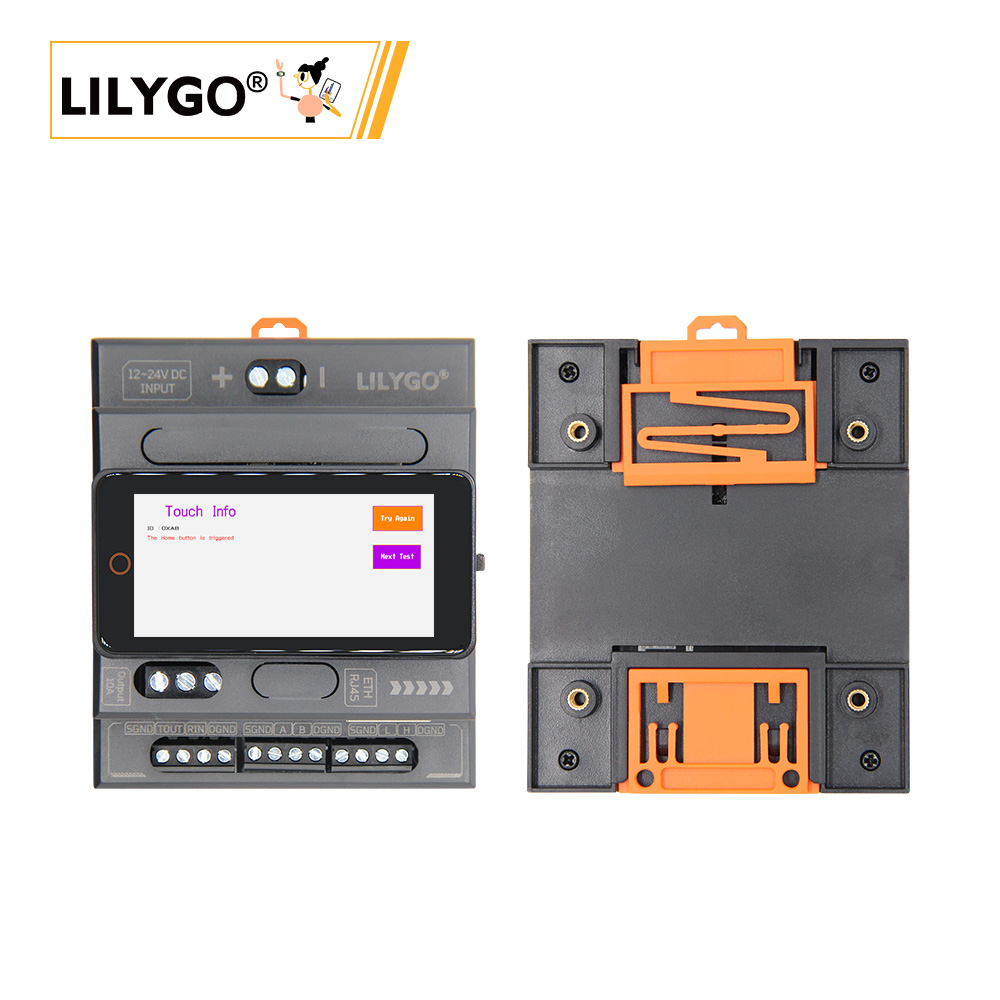
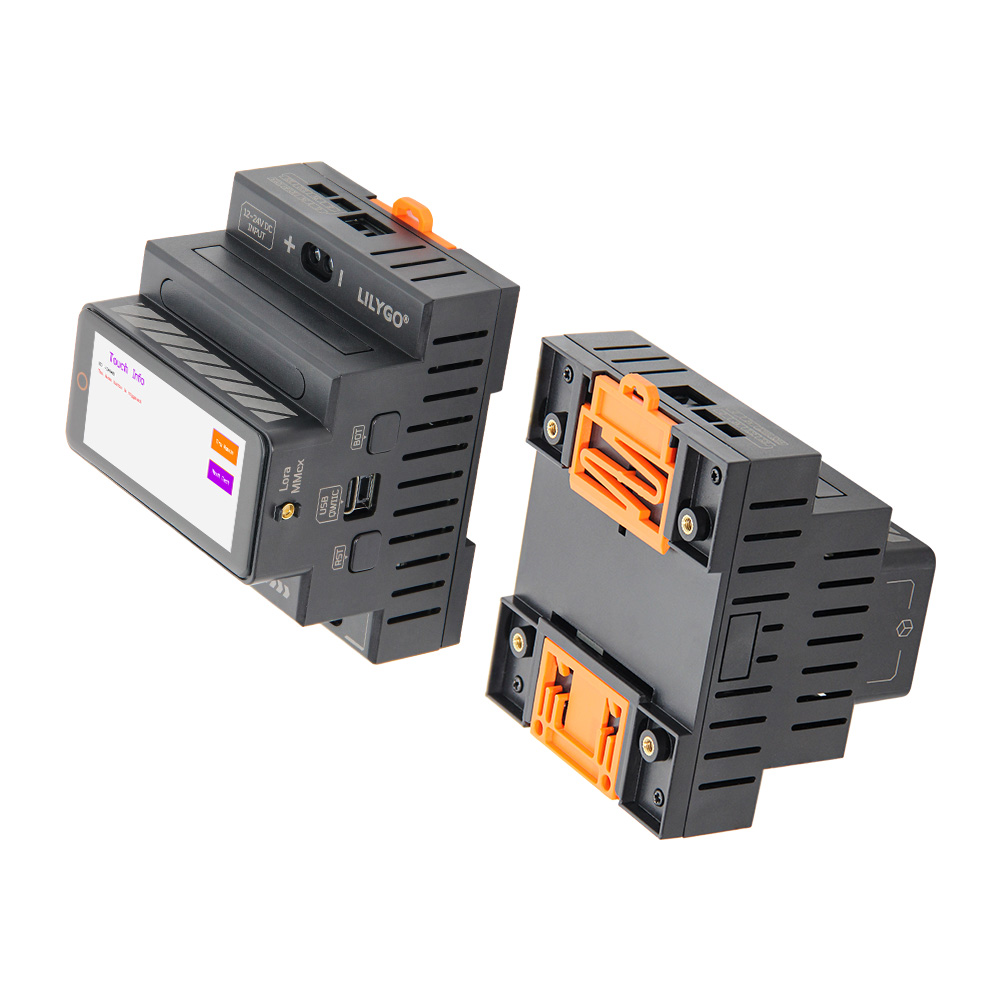
Physical Image
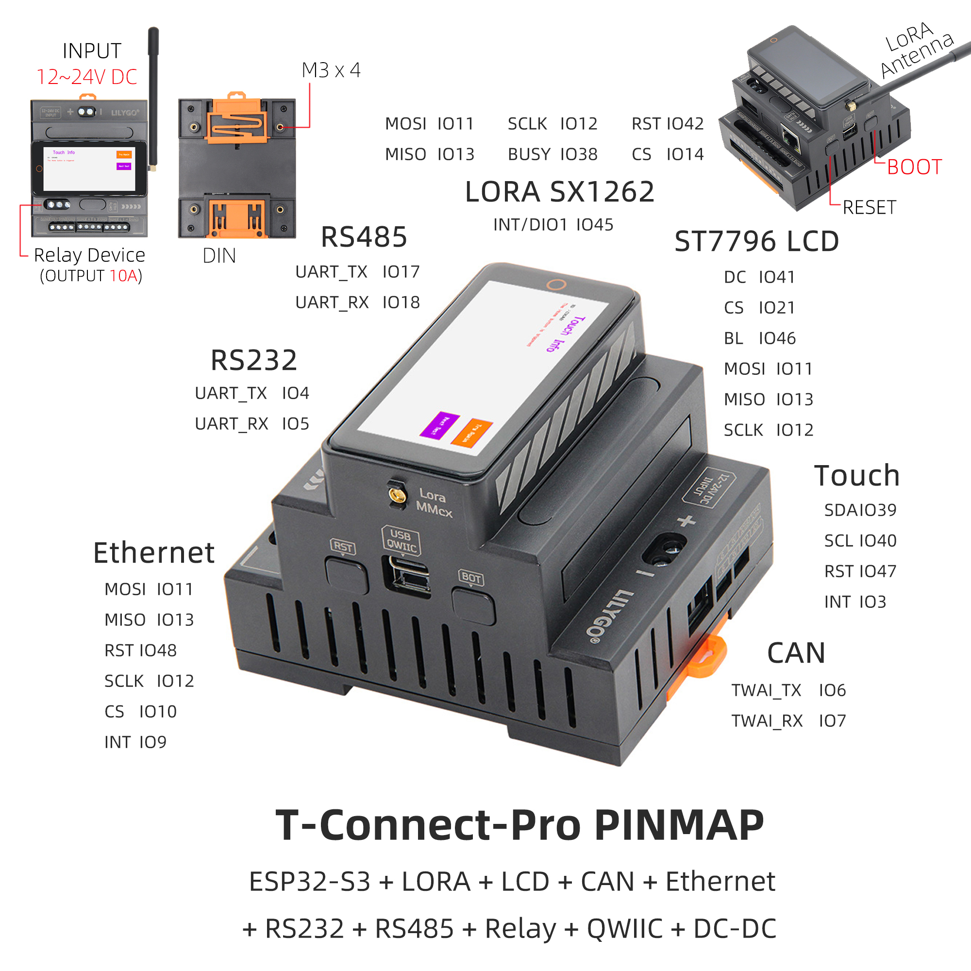
Pin Diagram
Modules
MCU
- Chip: ESP32-S3-R8
- PSRAM: 8M (Octal SPI)
- FLASH: 16M
- Related Information:
Espressif ESP32-S3 Datasheet
Display
- Resolution: 222x480px
- Display Type: TFT, LCD
- Driver Chip: ST7796
- Bus Communication Protocol: Standard SPI
- Dependent Library:
Arduino_GFX-1.4.6
Touch
- Chip: CST226SE
- Bus Communication Protocol: I2C
- Dependent Library:
Arduino_DriveBus-1.1.16
LoRa
- Module: HPD16A
- Chip: SX1262
- Bus Communication Protocol: Standard SPI
- Related Information:
HPD16A_V1.1
SX1262_V2.1 - Dependent Library:
RadioLib-6.6.0
CAN
- Module: TD501MCANFD
- Bus Communication Protocol: TWAI
- Related Information:
TD501MCANFD
RS485
- Module: TD501D485H-A
- Bus Communication Protocol: UART
- Related Information:
TD501D485H-A
RS232
- Module: TD501D232H
- Bus Communication Protocol: UART
- Related Information:
TD501D232H
Ethernet
- Chip: W5500
- Bus Communication Protocol: Standard SPI
- Dependent Library:
Ethernet_V2.0.0
Overview
T-Connect-Pro is based on the main control chip ESP32S3, consisting of 3-layer boards stacked together to form a product with rich and diverse functions. It features 3 different communication modules: CAN, RS485, RS232 for long-distance transmission, has an Ethernet interface, a relay interface, a LoRa module (SX1262), and is equipped with an LCD screen for more convenient operation.
| Component | Description |
|---|---|
| MCU | ESP32-S3-R8 |
| FLASH | 16MB |
| PSRAM | 8MB |
| Axis Sensor | BMA423 (I²C) |
| Ethernet | W5500 (SPI) |
| LoRa | HPD16A Module SX1262 Chip, 433~920MHz (selectable) |
| CAN | TD501MCANFD (TWAI) |
| RS485 | TD501D485H-A (UART) |
| RS232 | TD501D232H (UART) |
| Relay | 10A Output |
| Power Management | AXP2101 PMU |
| Display | ST7796 TFT LCD, 222×480px (SPI) |
| Touch | CST226SE (I²C) |
| Wireless | 2.4 GHz Wi-Fi & Bluetooth 5 (LE) |
| USB | 1 × USB Port and OTG (TYPE-C) |
| Expansion Interface | 1 × QWIIC Interface |
| Buttons | 1 x RESET Button + 1 x BOOT Button (built-in) |
| Power Input | 12~24V DC + 5V/500mA USB |
| Mounting Holes | 4 × M3mm Screw Holes |
| Dimensions | With base 88×72×60mm |
Quick Start
Example Support
| Example | [Platformio IDE][espressif32-v6.5.0][Arduino IDE][esp32_v2.0.14] |
Description | Picture |
|---|---|---|---|
| CAN | |||
| CST226SE | |||
| Ethernet_HTTP | |||
| Ethernet_Relay | |||
| Ethernet_Scan | |||
| GFX | |||
| GFX_SX1262 | |||
| Original_Test | Factory Program | ||
| Relay | |||
| RS485 | |||
| RS485_2 | |||
| SX126x_Channel_Activity_Detection_Blocking | |||
| SX126x_Channel_Activity_Detection_Interrupt | |||
| SX126x_PingPong | |||
| SX1262_Receive_Interrupt | |||
| raw | |||
| ttn_abp | |||
| ttn_otaa |
| Firmware | Description | Picture |
|---|---|---|
| Original_Test | Factory Program |
PlatformIO
- Install Visual Studio Code, choose the installation according to your system type.
- Open the "Extensions" in the sidebar of Visual Studio Code (or use Ctrl+Shift+X to open extensions), search for the "PlatformIO IDE" extension and install it.
- While the extension is installing, you can go to GitHub to download the program. You can download the main branch program by clicking the green "<> Code" button, or download the "Releases" version from the sidebar.
- After the extension is installed, open the sidebar's Explorer (or use Ctrl+Shift+E to open it), click "Open Folder", find the project code you just downloaded (the entire folder), click "Add", and the project files will be added to your workspace.
- Open the "platformio.ini" file in the project folder (PlatformIO will automatically open the "platformio.ini" of the corresponding folder after successfully adding the folder). Under the "[platformio]" section, uncomment and select the example program you want to upload (marked with "default_envs = xxx"). Then click the "√" at the bottom left to compile. If the compilation is successful, connect the microcontroller to the computer and click the "→" at the bottom left to upload.
Arduino
- Install Arduino IDE, choose the installation according to your system type.
- Open the "example" directory in the project folder, select the example project folder, and open the file ending with ".ino" to open the Arduino IDE project workspace.
- Open the "Tools" menu in the upper right corner -> Select "Board" -> "Board Manager", find or search for "esp32", and download the board files by the author "Espressif Systems". Then return to the "Board" menu and select the development board type under "ESP32 Arduino".
- Open the "File" -> "Preferences" menu, find the "Sketchbook location" field, and copy all the library files along with their folders from the "libraries" folder in the project directory to the "libraries" folder in this directory.
- Select the correct settings in the "Tools" menu as shown in the table below.
ESP32-S3
| Setting | Value |
|---|---|
| Board | ESP32S3 Dev Module |
| Upload Speed | 921600 |
| USB Mode | Hardware CDC and JTAG |
| USB CDC On Boot | Enabled |
| USB Firmware MSC On Boot | Disabled |
| USB DFU On Boot | Disabled |
| CPU Frequency | 240MHz (WiFi) |
| Flash Mode | QIO 80MHz |
| Flash Size | 16MB (128Mb) |
| Core Debug Level | None |
| Partition Scheme | 16M Flash (3MB APP/9.9MB FATFS) |
| PSRAM | OPI PSRAM |
| Arduino Runs On | Core 1 |
| Events Run On | Core 1 |
- Select the correct port.
- Click the "√" in the upper right corner to compile. If the compilation is successful, connect the microcontroller to the computer and click the "→" in the upper right corner to upload.
Development Platforms
Pin Overview
| Display Pins | ESP32S3 Pins |
|---|---|
| MOSI | IO11 |
| MISO | IO13 |
| DC | IO41 |
| SCLK | IO12 |
| CS | IO21 |
| BL | IO46 |
| Touch Pins | ESP32S3 Pins |
|---|---|
| SDA | IO39 |
| SCL | IO40 |
| RST | IO47 |
| INT | IO3 |
| Ethernet Pins | ESP32S3 Pins |
|---|---|
| MOSI | IO11 |
| MISO | IO13 |
| RST | IO48 |
| SCLK | IO12 |
| CS | IO10 |
| INT | IO9 |
| LoRa Pins | ESP32S3 Pins |
|---|---|
| MOSI | IO11 |
| MISO | IO13 |
| RST | IO42 |
| SCLK | IO12 |
| CS | IO14 |
| INT/DIO1 | IO45 |
| BUSY | IO38 |
| RS485 Pins | ESP32S3 Pins |
|---|---|
| UART_TX | IO17 |
| UART_RX | IO18 |
| RS232 Pins | ESP32S3 Pins |
|---|---|
| UART_TX | IO4 |
| UART_RX | IO5 |
| CAN Pins | ESP32S3 Pins |
|---|---|
| TWAI_TX | IO6 |
| TWAI_RX | IO7 |
Related Tests
FAQ
What should I do if I still don't know how to set up the programming environment after reading the above tutorial?
If you still don't understand how to set up the environment after reading the above tutorial, you can refer to the LilyGo-Document for setup instructions.
Why does Arduino IDE prompt me to update library files when I open it? Should I update or not?
Do not update the library files. Different versions of library files may not be compatible with each other, so updating is not recommended.
What frequency bands does the LoRa module support?
The LoRa module supports the 433~920MHz frequency bands. Specific frequency band versions can be selected based on requirements.
Why does my board keep failing to upload the program?
Please hold the "BOOT" button and try uploading the program again.
Are there any GPIO ports on the T-Connect Pro that are internally reserved or should not be used for external I/O modules?
All GPIO ports on the T-Connect Pro are already used. There are other ports available for external use.
What is the recommended method for expanding external input/output?
Use an I²C I/O expander.
Are there any known limitations or pin conflict issues when using LoRa (SX1262) together with Wi-Fi or Bluetooth?
No, Wi-Fi is a built-in function of the chip.
Is it safe to power external low-power I/O modules from the main board, or is it recommended to use an external power supply?
It is safe, and the main board can directly power sensors or low-current expansion devices. However, using an external power supply is recommended.
Are there any reference designs or examples for connecting external I/O or control modules to this board?
No, only the examples provided are supported.
Projects
Resources
Dependent Libraries
- Touch: Arduino_DriveBus-1.1.2
- LoRa: RadioLib-6.6.0
- Display: Arduino_GFX
- Ethernet: Ethernet_V2.0.0