


 English
LILYGO T3-S3 E-paper
Version History
| Version | Update date | Update description |
|---|---|---|
| T3-S3-E-paper_V1.0 | 2023-12-16 | Initial hardware version |
| T3-S3-E-paper_V1.1 | 2024-03-10 | Software optimization update |
Purchase Links
| Product | SOC | FLASH | PSRAM | Link |
|---|---|---|---|---|
| T3-S3 E-paper | ESP32-S3 | 4MB | 2MB | LILYGO Store |
Table of Contents
- Description
- Preview
- Modules
- Quick Start
- Pin Overview
- Related Tests
- FAQ
- Projects
- Resources
- Dependent Libraries
Description
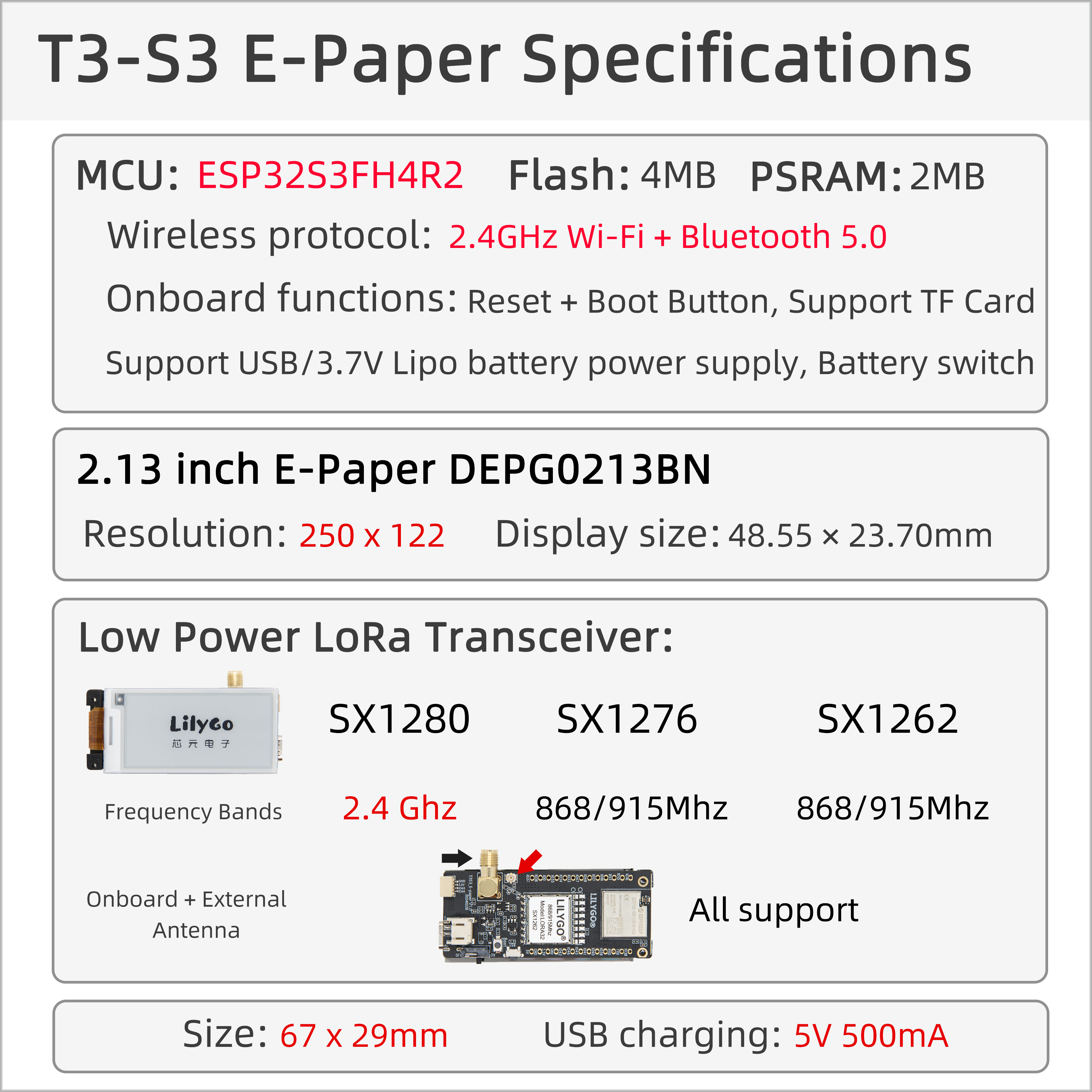
The T3-S3 E-Paper is a low-power IoT development board based on the ESP32S3FH4R2 microcontroller. It integrates 2.4GHz Wi-Fi and Bluetooth 5.0 dual-mode wireless communication, and supports various LoRa radio frequency modules (including SX1280, SX1276, SX1262), covering 2.4GHz and 868/915MHz frequency bands, making it suitable for long-range, low-power data transmission scenarios. Its core features a 2.13-inch E-ink display (DEPG0213BN) with a resolution of 250×122 and a compact screen size (48.55×23.70mm), combining low power consumption with high visibility, ideal for static information display needs (such as electronic labels, environmental monitoring). Hardware configuration includes 4MB Flash and 2MB PSRAM, supports SD card expansion storage, and provides dual power supply via USB or a 3.7V lithium battery (with battery switch), meeting the long battery life requirements of mobile devices. The onboard Reset/Boot buttons, multi-band antenna (onboard + external), and compact body design (67×29mm) make it widely applicable in fields such as smart agriculture, industrial sensing, and smart warehousing.
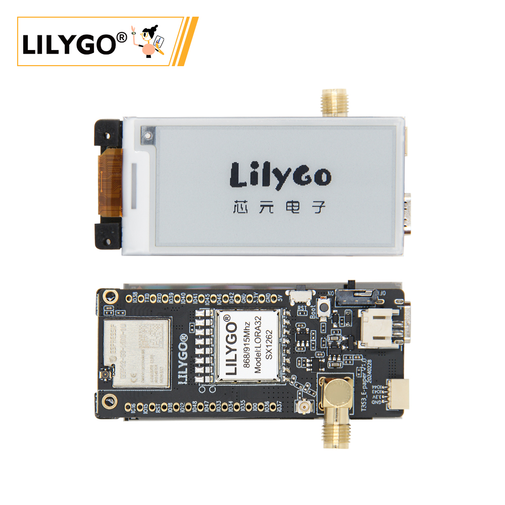
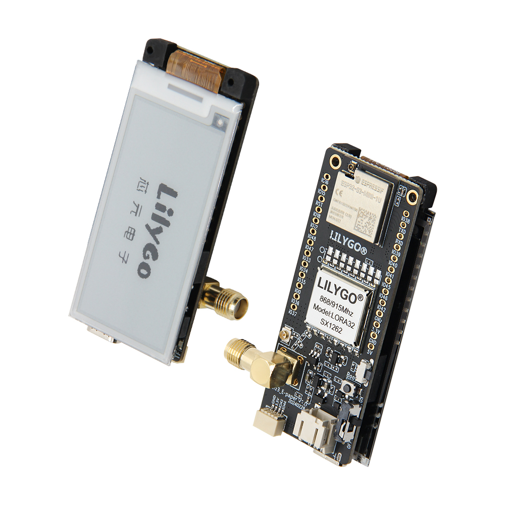
Preview
Physical Image
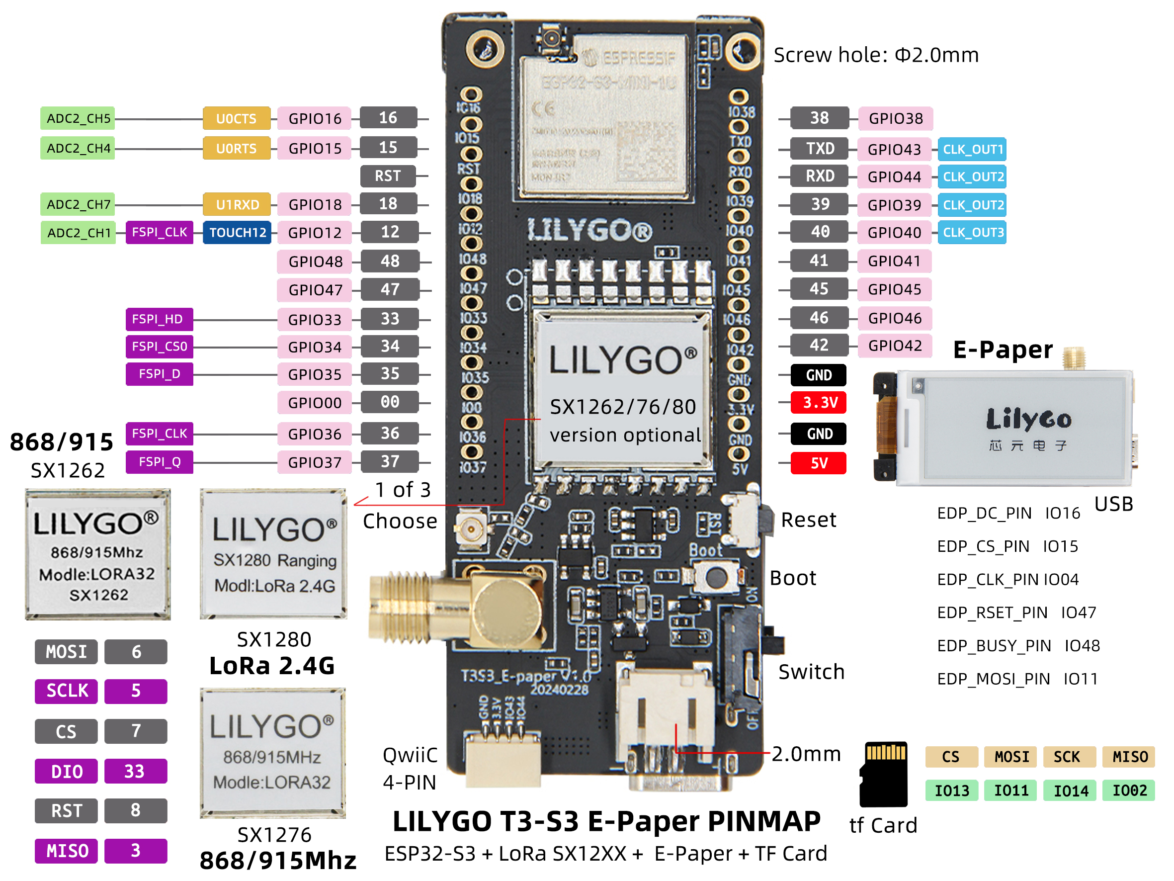
Pin Diagram
Modules
MCU
- Chip: ESP32-S3FH4R2
- PSRAM: 2MB (OPI PSRAM)
- FLASH: 4MB
- Wireless: 2.4 GHz Wi-Fi & Bluetooth 5 (LE)
Display
- Size: 2.13-inch E-ink display
- Resolution: 250×122px
- Display Type: E-Paper
- Driver Chip: DEPG0213BN
- Compatible Library: GxEPD
- Bus Communication Protocol: SPI
Wireless Communication
- LoRa Module: SX1280/SX1276/SX1262
- Frequency Band: 2.4GHz / 868MHz / 915MHz
- Feature: Multi-band support
Power Management
- Power Supply: USB Type-C / 3.7V Lithium Battery
- Battery Switch: Supports power switching
Overview
| Component | Description |
|---|---|
| MCU | ESP32-S3FH4R2 Dual-core LX7 |
| FLASH | 4MB |
| PSRAM | 2MB |
| Display | 2.13-inch DEPG0213BN E-Paper (250×122) |
| LoRa | SX1280 (2.4GHz) / SX1276/SX1262 (868/915MHz) |
| Storage | TF Card Expansion |
| Wireless | 2.4 GHz Wi-Fi & Bluetooth 5 (LE) |
| USB | 1 × USB Port (TYPE-C) |
| Expansion Interface | 1 × STEMMA QT/QWIIC Interface + FPC Antenna Interface |
| GPIO Interface | 2.54mm Pitch 2×13 Expansion IO Interface |
| Battery Interface | JST-GH 2MM Interface |
| Buttons | 1 x RESET Button + 1 x BOOT Button |
| Mounting Holes | 4 × 2mm Positioning Holes |
| Dimensions | 67 × 29 × 15 mm |
Quick Start
Example Support
| Example | PlatformIO/Arduino | ESP-IDF | Description |
|---|---|---|---|
| E-Paper_Display | ✓ | E-ink Display Example | |
| LoRa_Communication | ✓ | LoRa Communication Example | |
| SD_Card | ✓ | SD Card Read/Write Example |
PlatformIO
- Install Visual Studio Code, choose the installation according to your system type.
- Open the "Extensions" in the sidebar of Visual Studio Code (or use Ctrl+Shift+X to open extensions), search for the "PlatformIO IDE" extension and install it.
- While the extension is installing, you can go to GitHub to download the program. You can download the main branch program by clicking the green "<> Code" button, or download the "Releases" version from the sidebar.
- After the extension is installed, open the sidebar's Explorer (or use Ctrl+Shift+E to open it), click "Open Folder", find the project code you just downloaded (the entire folder), click "Add", and the project files will be added to your workspace.
- Open the "platformio.ini" file in the project folder (PlatformIO will automatically open the "platformio.ini" of the corresponding folder after successfully adding the folder). Under the "[platformio]" section, uncomment and select the example program you want to upload (marked with "default_envs = xxx"). Then click the "√" at the bottom left to compile. If the compilation is successful, connect the microcontroller to the computer and click the "→" at the bottom left to upload.
Arduino
- Install Arduino IDE, choose the installation according to your system type.
- Open the "example" directory in the project folder, select the example project folder, and open the file ending with ".ino" to open the Arduino IDE project workspace.
- Open the "Tools" menu in the upper right corner -> Select "Board" -> "Board Manager", find or search for "esp32", and download the board files by the author "Espressif Systems". Then return to the "Board" menu and select the "ESP32S3 Dev Module" board.
- Open the "File" -> "Preferences" menu, find the "Sketchbook location" field, and copy all the library files along with their folders from the "libraries" folder in the project directory to the "libraries" folder in this directory.
- Select the correct settings in the "Tools" menu as shown in the table below.
ESP32-S3
| Setting | Value |
|---|---|
| Board | ESP32S3 Dev Module |
| Upload Speed | 921600 |
| USB Mode | Hardware CDC and JTAG |
| USB CDC On Boot | Enabled |
| USB Firmware MSC On Boot | Disabled |
| USB DFU On Boot | Disabled |
| CPU Frequency | 240MHz (WiFi) |
| Flash Mode | QIO 80MHz |
| Flash Size | 4MB (32Mb) |
| Core Debug Level | None |
| Partition Scheme | Default 4MB with spiffs |
| PSRAM | OPI PSRAM |
| Arduino Runs On | Core 1 |
| Events Run On | Core 1 |
- Select the correct port.
- Click the "√" in the upper right corner to compile. If the compilation is successful, connect the microcontroller to the computer and click the "→" in the upper right corner to upload.
Development Platforms
Pin Overview
#define EDP_BUSY_PIN            48
#define EDP_RSET_PIN            47
#define EDP_DC_PIN              16
#define EDP_CS_PIN              15
#define EDP_CLK_PIN             14 // CLK
#define EDP_MOSI_PIN            11 // MOSI
#define EDP_MISO_PIN            -1

#define RADIO_SCLK_PIN          5
#define RADIO_MISO_PIN          3
#define RADIO_MOSI_PIN          6
#define RADIO_CS_PIN            7
#define RADIO_DIO1_PIN          33
#define RADIO_BUSY_PIN          34
#define RADIO_RST_PIN           8
#define RADIO_POW_PIN           35

//! SX1276/78 module only
#define RADIO_DIO0_PIN          9
#define RADIO_DIO3_PIN          21
#define RADIO_DIO4_PIN          10
#define RADIO_DIO5_PIN          36
//! end

#define SDCARD_MOSI             EDP_MOSI_PIN
#define SDCARD_SCLK             EDP_CLK_PIN
#define SDCARD_MISO             2
#define SDCARD_CS               13

#define BOARD_LED               37
#define LED_ON                  HIGH

#define BAT_ADC_PIN             1
#define BUTTON_PIN              0
Related Tests
E-Paper Performance
| Refresh Mode | Refresh Time | Power Consumption |
|---|---|---|
| Full Refresh | 2-3 seconds | Higher |
| Partial Refresh | 0.3-0.5 seconds | Lower |
| Sleep Mode | 0 seconds | Very Low |
FAQ
Q. How to adjust the external antenna resistor?
A. Refer to the image below to adjust the resistor direction for the external antenna: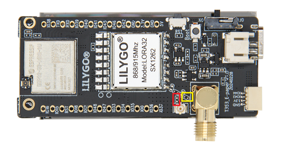
Q. Why is the E-ink display refresh rate relatively slow?
A. This is a characteristic of E-ink displays. A full-screen refresh takes 2-3 seconds, but after refreshing, no power is required to maintain the display, making it suitable for static information display.Q. Which LoRa modules are supported?
A. Supports multiple LoRa modules: SX1280 (2.4GHz), SX1276/SX1262 (868/915MHz).Q. What is the battery life?
A. In deep sleep mode, with an appropriately sized lithium battery, battery life can reach several weeks to months.Q. Why does my board fail to upload programs?
A. Please hold down the "BOOT" button and press the "RST" button simultaneously, then release the "RST" button to enter download mode, and try uploading the program again.