T-Display P4 get it now
Overview
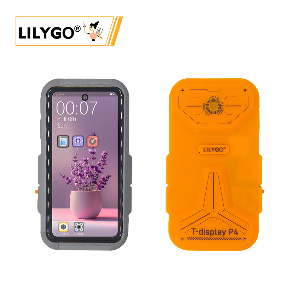
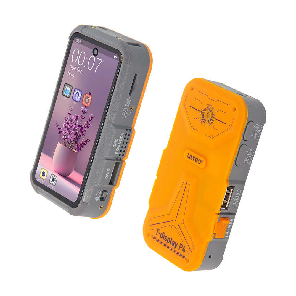
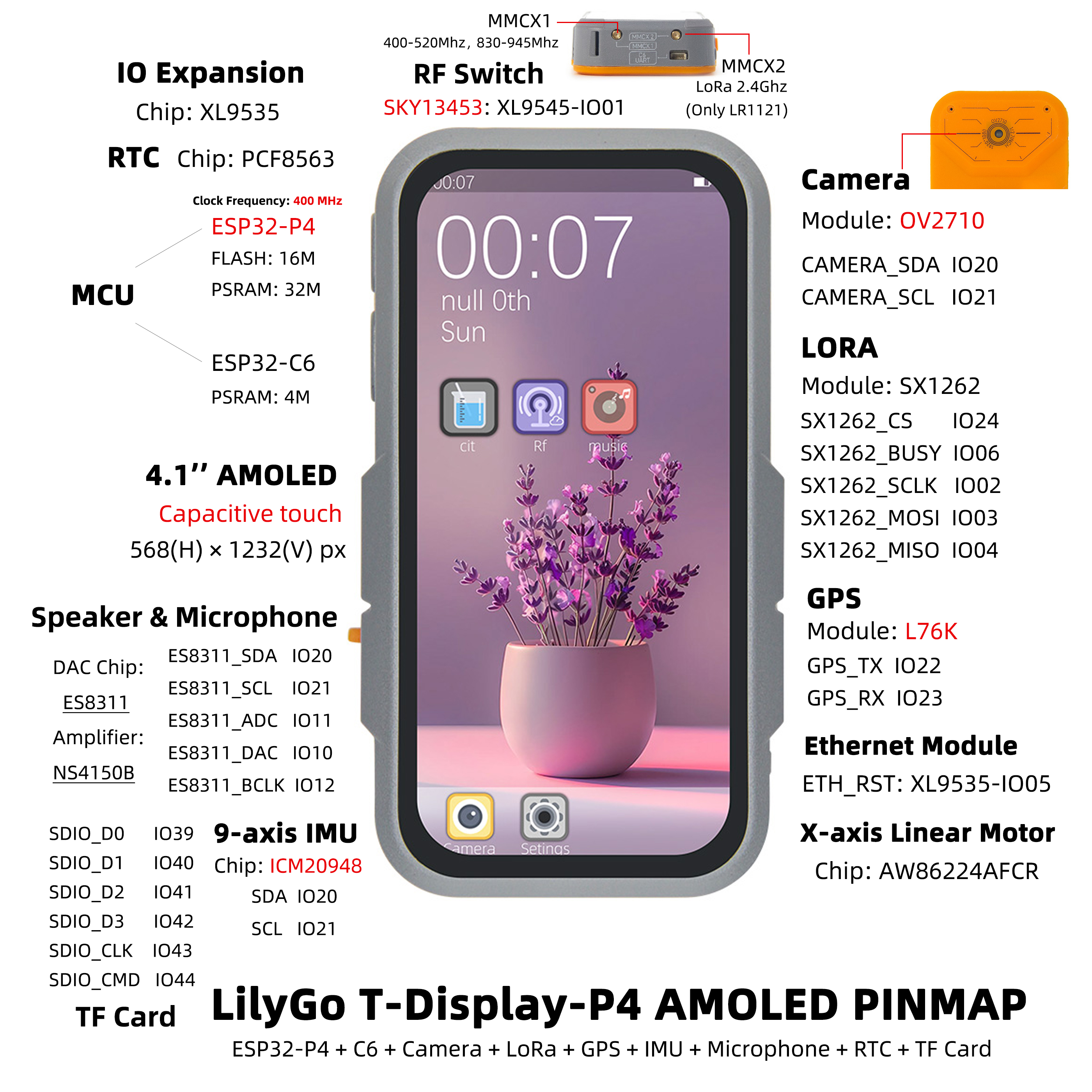
T-Display P4 is a multi-functional development board based on ESP32-P4 (16 MB Flash) for complex graphics, multimedia, and IoT applications. Features a 4.05-inch MIPI TFT (540 × 1168) or 4.1-inch AMOLED (568 × 1232) with capacitive touch, ESP32-C6 auxiliary processor (Wi-Fi 6 + Bluetooth 5.3, SDIO), SX1262 LoRa (HPD16A module), L76K GPS, ES8311 + NS4150B audio, AW86224 linear vibration motor, ICM20948 IMU, BQ27220 battery monitor, OV2710 MIPI camera. Supports keyboard expansion board (T-Display-P4-Keyboard) with CC1101, NRF24L01, and NFC (ST25R3916).
Hardware Notes
The RST button on T-Display P4 resets the ESP32-P4 main controller only. It is not a full board power reset. Some onboard peripheral power rails are controlled through I/O expanders such as XL9535, so resetting only the ESP32-P4 may not force every peripheral through a complete power-off and power-on cycle.
If the device enters download mode after power-on, does not boot normally, or cannot recover after pressing RST, turn the power switch off first, wait for the board capacitors to discharge, and then turn the device on again. Do not hold BOOT during power-on; BOOT may put the ESP32-P4 into download mode, making the device appear unable to start normally.
USB-C Port Usage
T-Display P4 has two USB-C ports, but they are not interchangeable:
| Port | Purpose | Notes |
|---|---|---|
Right-side P4.U | ESP32-P4 data transfer, firmware flashing, serial terminal | Disable RTS / hardware flow control when using a serial terminal. The RTS line can reset the P4 and may cause the device to hang after reset. |
| Left-side USB-C | Charging / power input | Not intended for data transfer or firmware flashing. |
LoRa External Antenna Warning
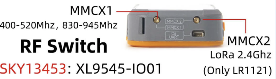
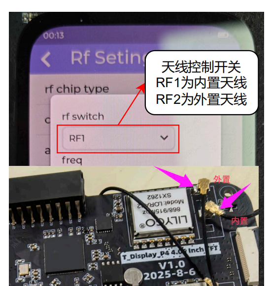
Before switching LoRa from the internal antenna to the external antenna in software, connect the included dipole antenna to the MMCX 1 connector first. Do not enable external antenna mode without an antenna connected, otherwise the SX1262 LoRa chip may be damaged.
Keyboard Expansion Installation
T-Display-P4-Keyboard uses a small daughterboard and Pogo Pins to connect to the P4 host. Power the device off before installation, and use tweezers or a magnifier if needed. During installation, check that the daughterboard pins are vertical, not bent, and actually enter the connector holes instead of sliding along the outside of the connector.
If the screen shows xl9555 init fail or many init fail messages, first check whether the keyboard daughterboard and side QWIIC / expansion connector are aligned and making full contact, then power-cycle the device.
Quick Start
Example Support
| Example | ESP-IDF | Description |
|---|---|---|
| sx1262_lora_send_receive | ✓ | SX1262 LoRa send/receive |
| es8311_sd_wav | ✓ | Audio codec and SD WAV playback |
| xiaozhi | ✓ | XiaoZhi AI chatbot |
ESP-IDF (Primary)
- Install Visual Studio Code and the ESP-IDF extension
- Clone the repository:shell
git clone --recursive https://github.com/Xinyuan-LilyGO/T-Display-P4.git git submodule update --init --recursive - Install ESP-IDF v5.4.1 and configure the extension
- Open "SDK Configuration Editor", select the example to build and the screen type, click Save
- Set target to ESP32P4, click "Build Project", then "Flash Project"
PlatformIO
- Install Visual Studio Code and the PlatformIO IDE extension
- Open the
T-Display-P4project folder - Open
platformio.iniand select your example - Click ✓ to compile, click → to upload
Arduino
Configure board as ESP32P4 Dev Module with appropriate settings when Arduino ESP32 adds ESP32-P4 support.
Development Platforms
- ESP-IDF — Primary platform
- Arduino IDE
- PlatformIO
- MicroPython
Video
Key Features
- ESP32-P4 (16 MB Flash), ESP32-C6 co-processor (Wi-Fi 6 + BT 5.3, SDIO)
- 4.05" MIPI TFT (540 × 1168) or 4.1" AMOLED (568 × 1232), 10-point capacitive touch
- SX1262 LoRa (HPD16A module), L76K GPS, PCF8563 RTC
- ES8311 + NS4150B audio, AW86224 linear vibration motor
- ICM20948 9-axis IMU, BQ27220 battery monitor, LGS4056H charger
- OV2710 MIPI camera, XL9535 I/O expander
- Keyboard expansion: CC1101, NRF24L01, NFC (ST25R3916), TCA8418 keyboard driver
Product Parameters
| Feature | Specification |
|---|---|
| MCU | ESP32-P4 |
| Flash | 16 MB |
| Co-processor | ESP32-C6-FH4, 4 MB PSRAM, SDIO |
| Wi-Fi | Wi-Fi 6 (ESP32-C6) |
| Bluetooth | Bluetooth 5.3 LE (ESP32-C6) |
| Display | 4.05" MIPI TFT (540×1168) / 4.1" AMOLED (568×1232) |
| Touch | 10-point capacitive |
| LoRa | SX1262 (HPD16A module) |
| GPS | L76K |
| RTC | PCF8563 |
| Audio | ES8311 codec + NS4150B amplifier |
| Vibration | AW86224 linear motor |
| IMU | ICM20948 nine-axis |
| Battery Monitor | BQ27220 |
| Camera | OV2710 (MIPI) |
| I/O Expander | XL9535 |
| USB | 2 × USB-C (right-side P4.U for data / flashing, left-side USB-C for charging / power) |
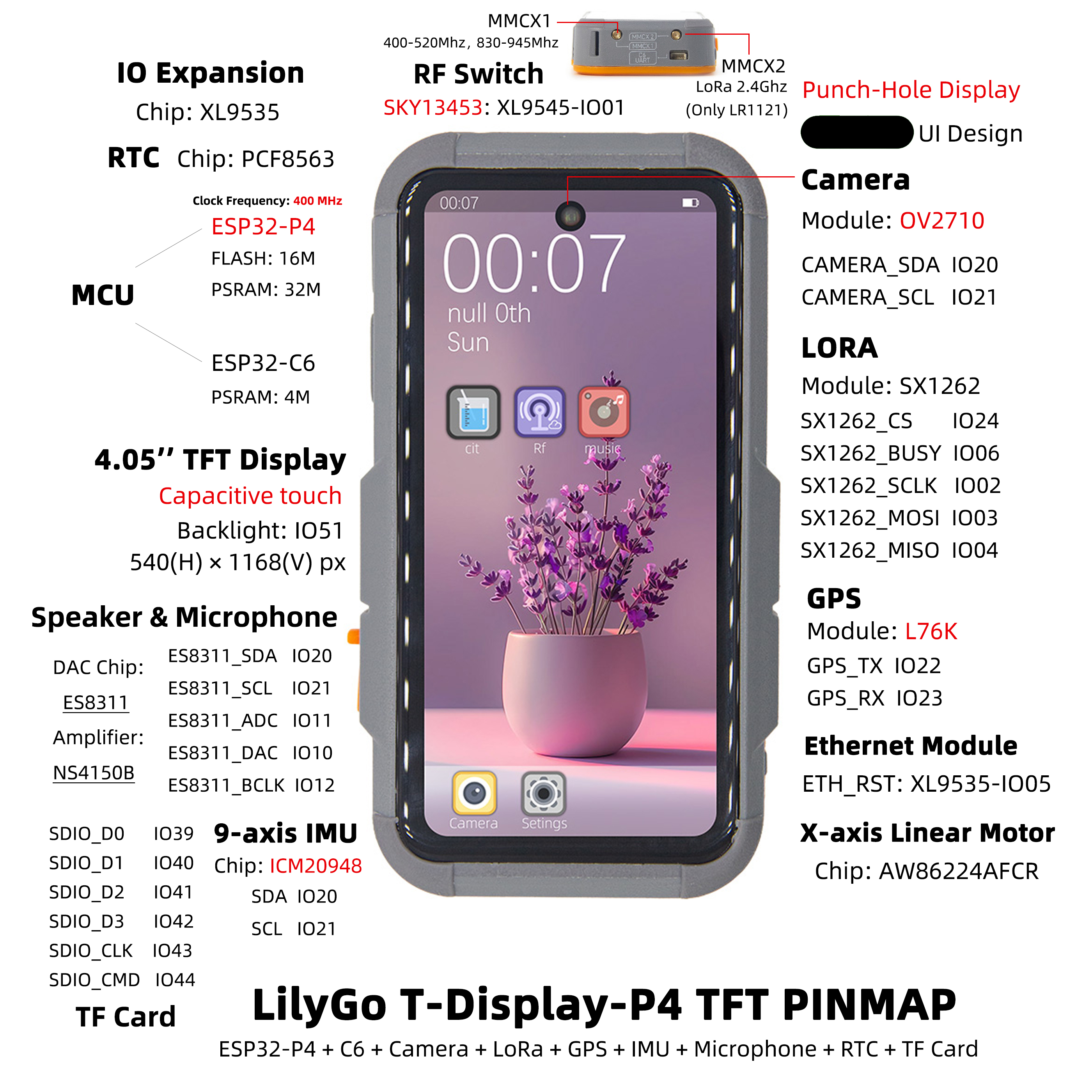
Pin Diagram
AMOLED Version
TFT Version
Dimension Diagram
Schematic
Datasheet
Software Development
Dependent Libraries
- (ESP-IDF based — all dependencies managed via IDF component manager)
FAQ
Q. Why does my board keep failing to upload programs? A. Hold down the BOOT button and try uploading again.
Q. Why does the screen show many
init failinitialization errors? A. This is usually caused by the side QWIIC / expansion connector or keyboard daughterboard not being fully seated. Power off the board first, then check whether the connector is fully inserted, tilted, whether the Pogo Pins are aligned with the connector holes, and whether any pins are bent or loose. Power the board on again after reconnecting it.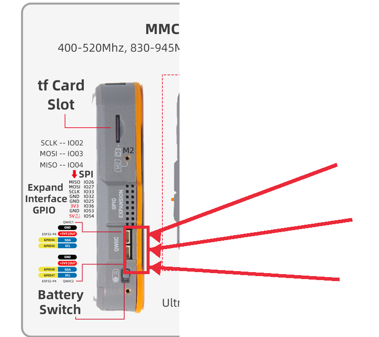
Q. What should I watch out for when using the external LoRa antenna? A. Before switching LoRa to external antenna mode, connect the included dipole antenna to MMCX 1. Do not enable external antenna mode with no antenna connected, otherwise the SX1262 LoRa chip may be damaged.
Q. Can both USB-C ports flash firmware? A. No. The right-side
P4.Uport is for data transfer and firmware flashing. The left-side USB-C port is for charging / power only. Disable RTS / hardware flow control when using a serial terminal onP4.U.Q. Keyboard test output is incorrect? A. Known feedback:
Shift + hshould output comma,, but some keyboard test application versions output apostrophe', and the'key position is incorrect. Update to a later fixed keyboard test firmware or application.Q. ESP32-C6 cannot connect to Wi-Fi? A. First update the ESP32-C6 coprocessor firmware using the C6 flashing flow in Quick Start, then flash the ESP32-P4 main processor back to factory firmware or a normal application firmware. If the latest firmware still cannot connect to Wi-Fi, record the C6 firmware version, P4 firmware version, and connection log for feedback.
Q. Why can't I get a GPS fix in the factory firmware? A. Test outdoors or in an area with good GPS signal. Check the latest factory firmware.
Q. Battery not charging when powered off or battery life very short? A. T-Display-P4 supports charging when off. Factory firmware runs ~3–5 hours (no sleep). For sleep, use the
deep_sleepexample.Q. ESP-IDF menuconfig reports
asyncio.exceptions.LimitOverrunError? A. This is a bug in esp-idf v5.4–v5.5. Inesp-idf-v5.x/tools/idf_py_actions/tools.pyline 351, changelimit=1024 * 256tolimit=1024 * 512.
Version History
| Version | Release Date | Update Description |
|---|---|---|
| T-Display-P4 V1.0 | 2025-06-13 | Initial version |
| T-Display-P4-Keyboard V1.0 | 2025-09-12 | Keyboard expansion board initial version |