T-Relay get it now
Overview
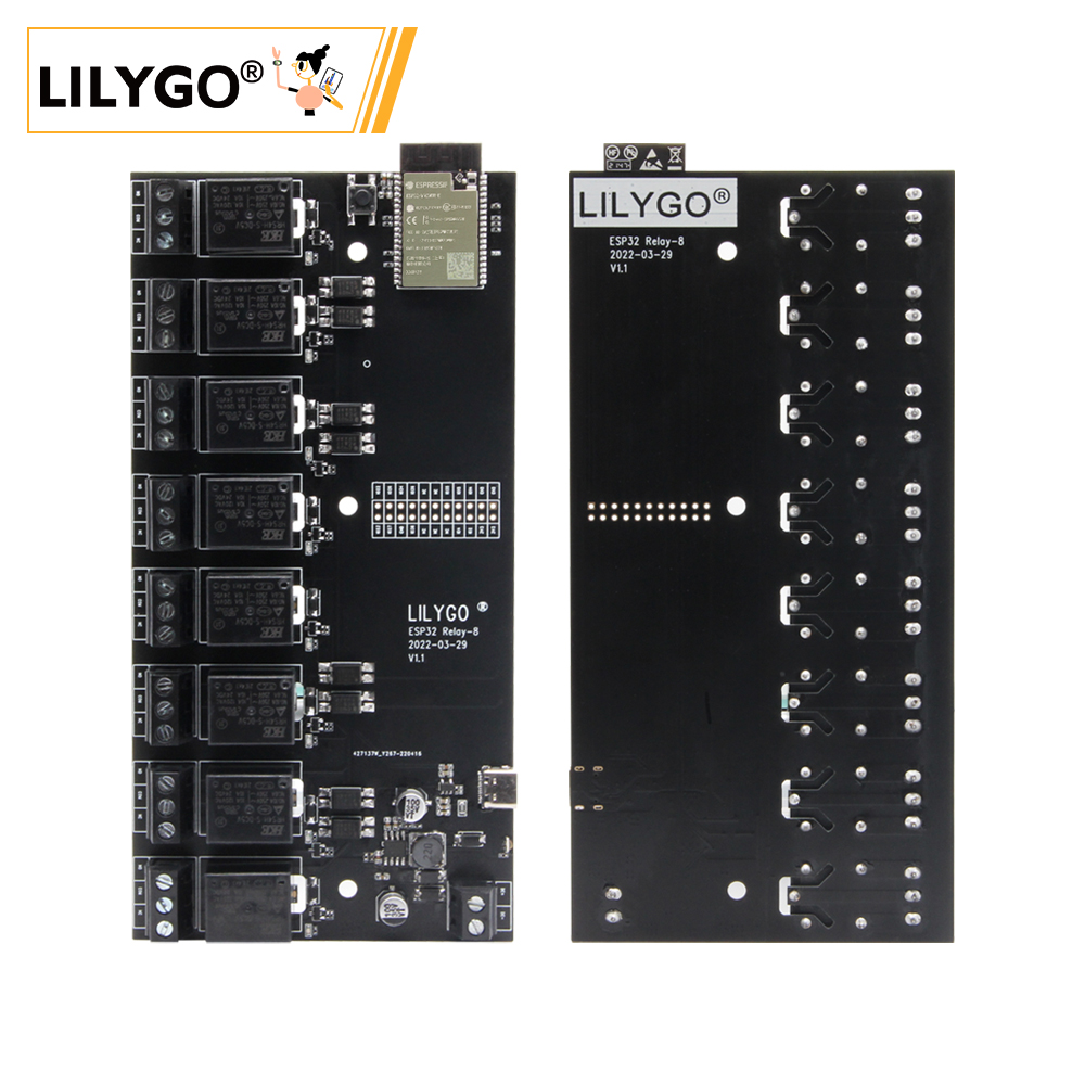
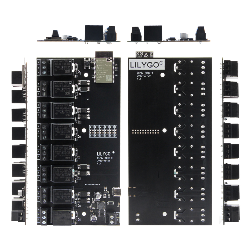
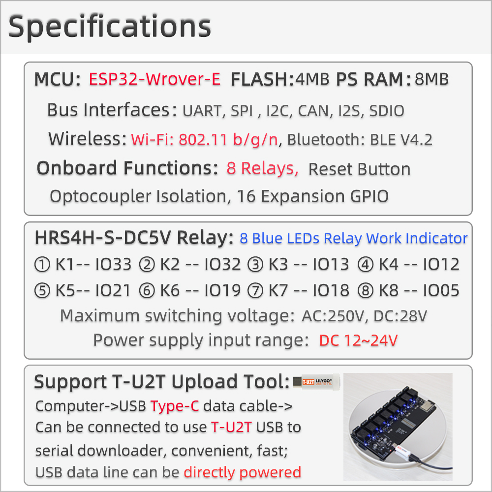
LILYGO T-Relay is an ESP32-based development board with integrated relay outputs. Powered by the ESP32-WROVER-E module (dual-core Xtensa LX6, 240 MHz), it combines Wi-Fi 4 (802.11 b/g/n) and Bluetooth 4.2 with 4 optocoupler-isolated relay channels capable of switching up to 250 V AC / 10 A or 28 V DC / 10 A. The board accepts a wide 5–24 V DC power input, exposes spare GPIOs on a header, and is compatible with Tasmota, ESPHome, and other ESP32 firmware frameworks. Ideal for smart home automation, remote switching, and industrial control applications.
Quick Start
Example Support
| Example | PlatformIO/Arduino | ESP-IDF | Description |
|---|---|---|---|
| LilyGo-T-Relay | ✓ | Relay control, ESPHome, Tasmota examples |
PlatformIO
- Install Visual Studio Code and Python
- Search for and install the PlatformIO IDE extension in VS Code
- Open the
LilyGo-T-Relayproject folder - Open
platformio.iniand select your example - Click ✓ to compile, connect via USB-C, click → to upload
Note: The board cannot be flashed via USB without the LilyGO T-U2T USB-to-serial adapter. Use the T-U2T or another CP210x/CH340 adapter connected to the UART header.
Arduino
- Install Arduino IDE
- Install Arduino ESP32
- In Tools → Board, select ESP32 Wrover Module
- Set Partition Scheme to Huge APP (3MB No OTA/1MB SPIFFS)
- Set PSRAM to Enabled
- Click Upload
Related Videos
Key Features
- ESP32-WROVER-E dual-core Xtensa LX6 @ 240 MHz, Wi-Fi + Bluetooth 4.2
- 4 optocoupler-isolated relay channels (HRS4H-S-DC5V)
- Relay contacts: 250 V AC / 10 A or 28 V DC / 10 A
- Wide input voltage: 5–24 V DC
- 4 MB Flash, 8 MB PSRAM
- Blue LED status indicator per relay channel
- All spare GPIOs broken out on a pin header
- Compatible with Tasmota, ESPHome, ESPEasy
Specifications
| Parameter | Value |
|---|---|
| SOC | ESP32-WROVER-E (Xtensa dual-core LX6, 240 MHz) |
| Flash | 4 MB |
| PSRAM | 8 MB |
| Wireless | Wi-Fi 802.11 b/g/n, Bluetooth 4.2 |
| Relay Channels | 4 |
| Relay Rating | 250 V AC / 10 A, 28 V DC / 10 A |
| Input Voltage | 5–24 V DC |
| Logic Voltage | 3.3 V |
| USB | USB-C (power only; serial via T-U2T adapter) |
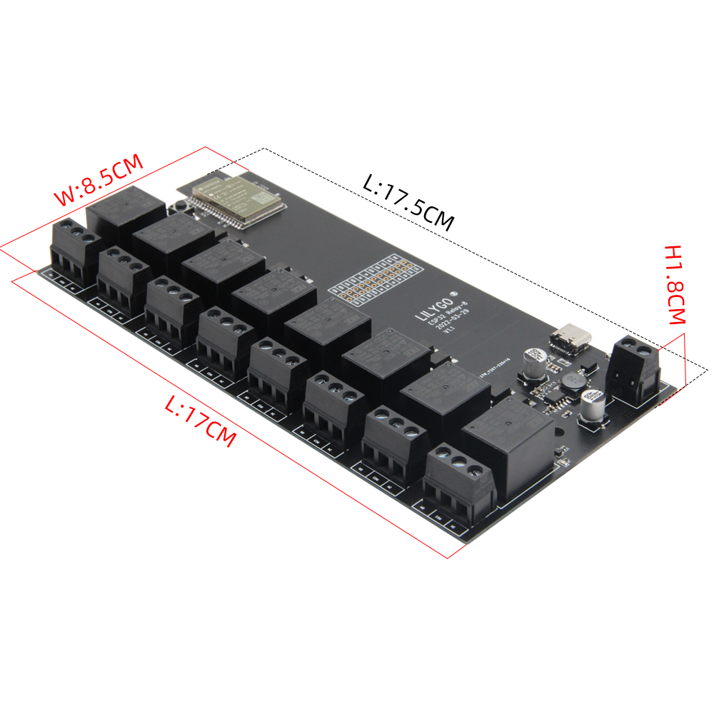
| Dimensions | |
| Weight |
Pin Diagram
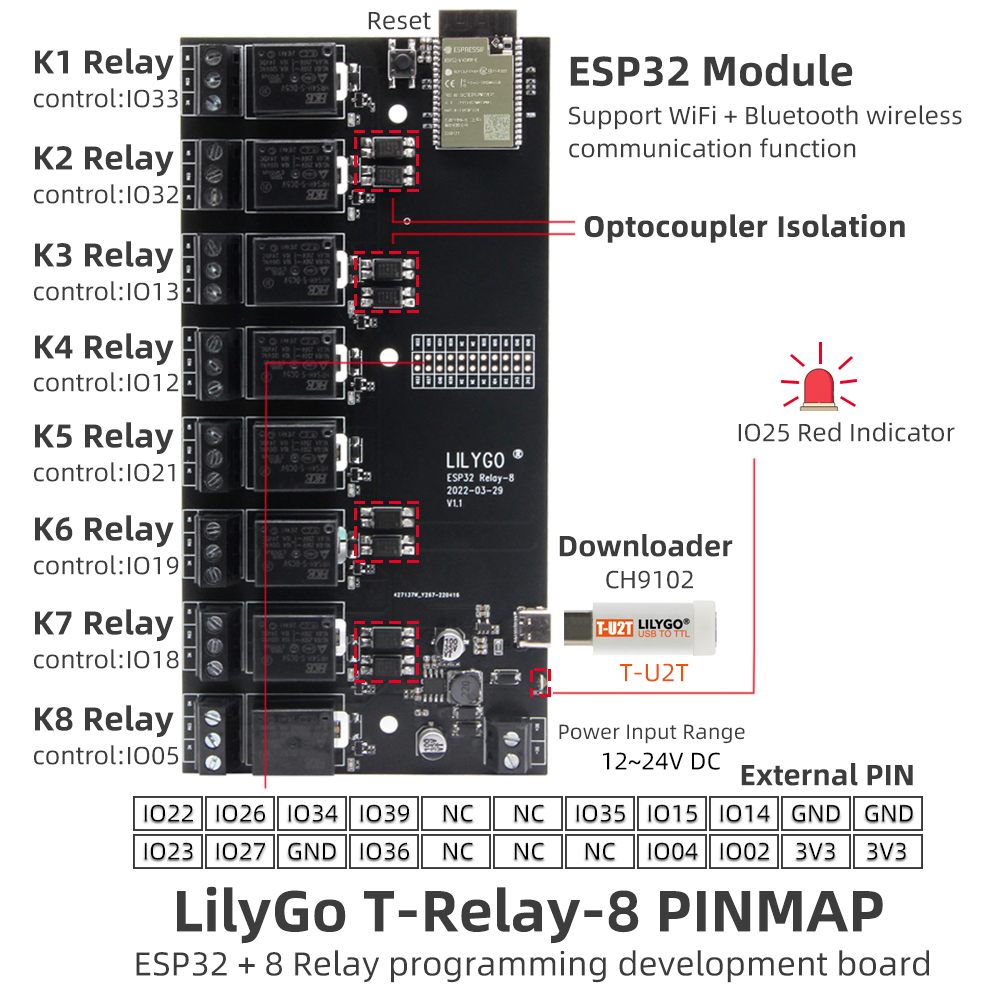
| Relay | GPIO |
|---|---|
| K1 | GPIO21 |
| K2 | GPIO19 |
| K3 | GPIO18 |
| K4 | GPIO5 |
Dimensions
Schematic
Datasheet
Software Libraries
Tasmota
FAQ
Changelog
| Version | Date | Notes |
|---|---|---|
| V1.0 | Initial release |