
Dashcam
A dashcam firmware for the LILYGO T-CameraPlus-S3 development board. Records camera video and microphone audio into standard AVI files saved to a microSD card, with real-time preview on the LCD.
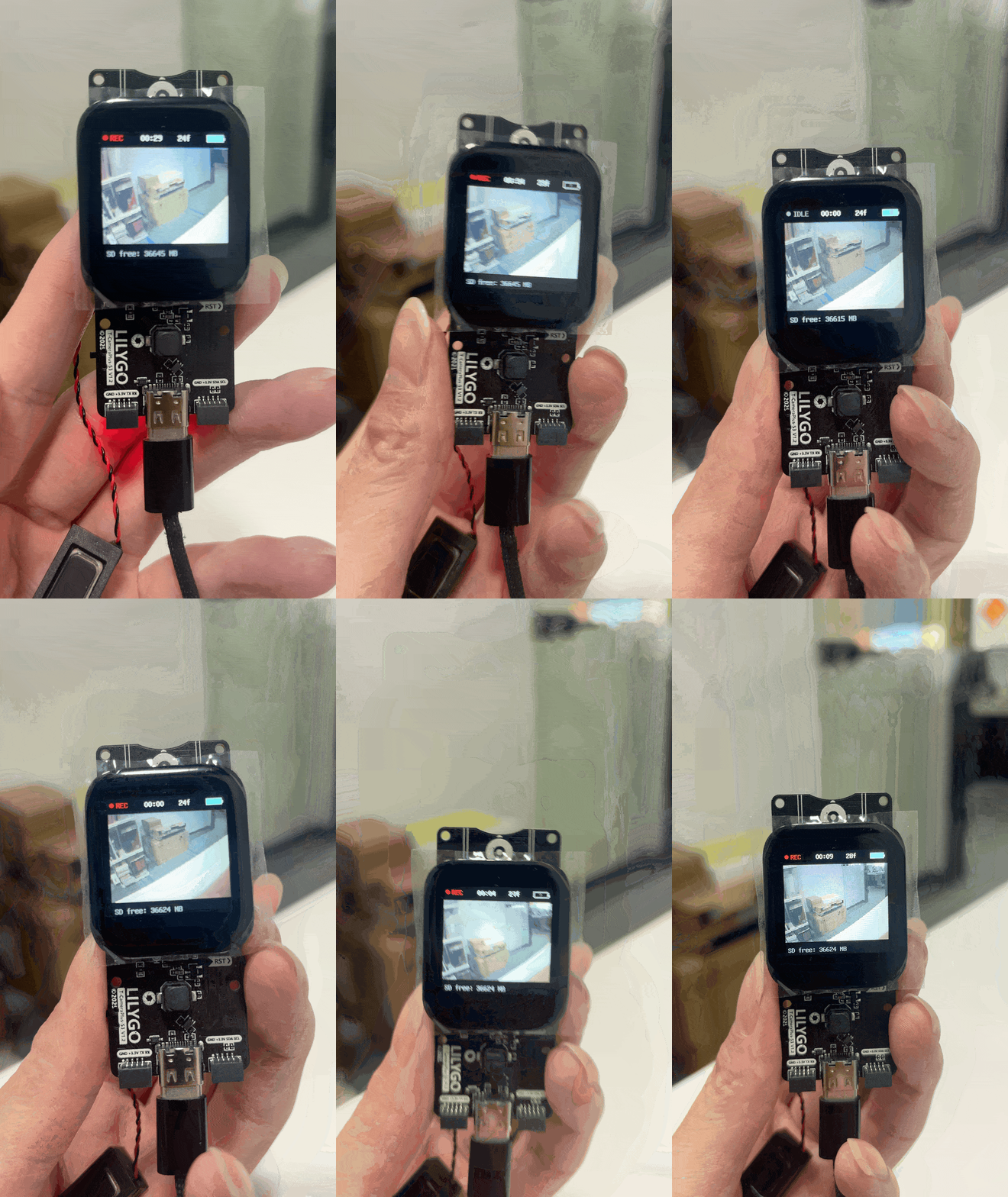
Hardware Requirements
| Component | Specification |
|---|---|
| Board | LILYGO T-CameraPlus-S3 V1.2 |
| MCU | ESP32-S3, 240 MHz, 16 MB Flash, 8 MB PSRAM |
| Display | 240×240 ST7789V LCD |
| Camera | OV2640 / OV5640 (auto-detected) |
| Microphone | MP34DT05TR digital microphone (PDM) |
| Storage | microSD card (Class 10 / U3 recommended, 32 GB+) |
| PMU | SY6970 power management |
| Touch | CST816S touchscreen |
Note: The pin definitions in
board_pins.hcorrespond to V1.2. V1.0 / V1.1 have different SPI, I2C, camera, and microphone pins — refer to the actual board silkscreen to make adjustments.
Features
- Loop recording: Automatically records video as AVI files (Motion-JPEG video + 16-bit PCM mono audio), with each clip defaulting to 60 seconds, stored in the
/dashcamdirectory on the SD card. - Loop overwrite: Automatically deletes the oldest clips when free SD card space drops below 150 MB, ensuring uninterrupted recording.
- Live preview: The recording is displayed in real time on the 240×240 LCD with an overlaid status bar (recording duration, free space, battery level, frame rate).
- Photo snapshot: Touch the screen or press KEY2 to save a JPEG photo to the
/photosdirectory on the SD card at any time. - Auto-start: Recording begins automatically on power-up (can be disabled in
config.h). - Audio recording: I2S digital microphone simultaneously captures 16 kHz mono audio and mixes it into the AVI file.
Flash Firmware
ESP32 烧录工具 (官方API)
选择固件
操作日志
Operation
| Action | Function |
|---|---|
| Power on | Recording starts automatically (AUTO_START_RECORDING=1) |
| Press KEY1 (GPIO 17) | Take a snapshot, saved to /photos, plays a confirmation tone |
| Press KEY2 (GPIO 0) | Toggle recording start / stop, plays a confirmation tone |
| Touch screen | Take a snapshot |
LCD Status Overlay
| Icon / Field | Meaning |
|---|---|
REC red dot | Currently recording |
00:01:23 | Elapsed time of the current clip |
1234 MB | Remaining SD card space |
85% | Battery level |
⚡ | Charging |
24 fps | Current recording frame rate |
File Structure
SD card
├── dashcam/
│   ├── CLIP_0001.avi
│   ├── CLIP_0002.avi
│   └── ...
└── photos/
    ├── IMG_0001.jpg
    └── ...
Key Configuration
All recording parameters are centralised in config.h — no source code changes required:
| Parameter | Default | Description |
|---|---|---|
REC_SEGMENT_SECONDS | 60 | Clip duration (seconds) |
REC_MIN_FREE_MB | 150 | Minimum free SD space; triggers loop deletion when exceeded |
CAM_JPEG_QUALITY | 14 | JPEG quality (lower value = higher quality, larger file) |
CAM_FRAMESIZE_OV2640 | SVGA 800×600 | OV2640 resolution |
CAM_FRAMESIZE_OV5640 | HD 1280×720 | OV5640 resolution, ~15fps (ESP32-S3 limited) |
AUDIO_ENABLE | 1 | Whether to record audio |
AUDIO_SAMPLE_RATE | 16000 | Audio sample rate (Hz) |
PREVIEW_EVERY_N_FRAMES | 6 | Update LCD preview every N frames |
AUTO_START_RECORDING | 1 | Whether to start recording automatically on power-up |
Build & Flash
PlatformIO (Recommended)
Requirements:
- VS Code + PlatformIO IDE extension
- Or PlatformIO Core CLI
Steps:
# 1. Enter the example directory
cd examples/Dashcam

# 2. Build
pio run

# 3. Flash (connect the board first)
pio run -t upload

# 4. Open serial monitor (115200 baud)
pio device monitor

# One-shot: build + flash + monitor
pio run -t upload && pio device monitor
After a successful build, the merge_bin.py post-processing script automatically merges the bootloader, partition table, and application firmware into a single flashable file:
firmware_out/T-CameraPlus-S3_Dashcam.binFlash the merged firmware directly (no build environment required):
esptool.py --chip esp32s3 --baud 921600 write_flash 0x0 firmware_out/T-CameraPlus-S3_Dashcam.binArduino IDE
Requirements:
- Arduino IDE 2.x
- ESP32 Arduino core 2.0.14 (installation guide)
Install required libraries (search in Library Manager):
| Library | Version |
|---|---|
| LovyanGFX | ^1.1.16 |
| JPEGDEC | ^1.6.2 |
| XPowersLib | ^0.2.6 |
| OneButton | ^2.5.0 |
Board settings (Tools menu):
| Option | Value |
|---|---|
| Board | ESP32S3 Dev Module |
| Flash Size | 16MB (128Mb) |
| Partition Scheme | Custom (manually import partitions.csv) |
| PSRAM | OPI PSRAM |
| Flash Mode | QIO 80MHz |
| USB Mode | Hardware CDC and JTAG |
| CPU Frequency | 240MHz (WiFi) |
| Upload Speed | 921600 |
Steps:
- Open
Dashcam.ino. - Configure the board options as shown above.
- Click Upload to build and flash.
- Open the Serial Monitor and set the baud rate to
115200.
Tip: Arduino IDE does not support directly importing a custom partition table file. It is recommended to add the partition scheme from
partitions.csvto the Arduino core'sboards.txtin advance, or use PlatformIO to avoid partition configuration issues.
Architecture
The firmware uses FreeRTOS dual-core parallelism:
| Task | Core | Priority | Responsibility |
|---|---|---|---|
recordTask | Core 1 | 5 | Camera capture, AVI muxing, SD write |
uiTask | Core 0 | 3 | LCD preview rendering, touch detection, button polling, PMU status |
| mic task (internal) | Core 0 | — | I2S capture → FreeRTOS Stream Buffer |
The LCD and microSD share the same SPI bus; a mutex (spibus::Guard) ensures safe concurrent access.
Unit Tests (AVI Writer, Host-only)
The AVI writer module can be tested independently without hardware:
g++ -std=c++14 -I../../src test/host/test_avi.cpp avi_writer.cpp -o test_avi
./test_avi
Troubleshooting
Recording does not start / LCD shows "NO SD CARD"
- Check that the SD card is inserted and formatted as FAT32 or exFAT.
- Recommended: 32 GB or larger, Class 10 / U3.
No audio
- Check that
AUDIO_ENABLEis set to1inconfig.h. - Check that
AUDIO_I2S_CHANNELmatches the microphone channel on your board.
Low frame rate
- Increasing
CAM_JPEG_QUALITY(higher numeric value) reduces file size and improves frame rate. - Increasing
PREVIEW_EVERY_N_FRAMESreduces the time the LCD occupies the SPI bus, freeing more bandwidth for SD writes.
V1.0 / V1.1 board not working correctly
- The pin definitions in
board_pins.hare based on V1.2. Refer to the official schematic and update the pin numbers accordingly.