T-Connect get it now
Overview
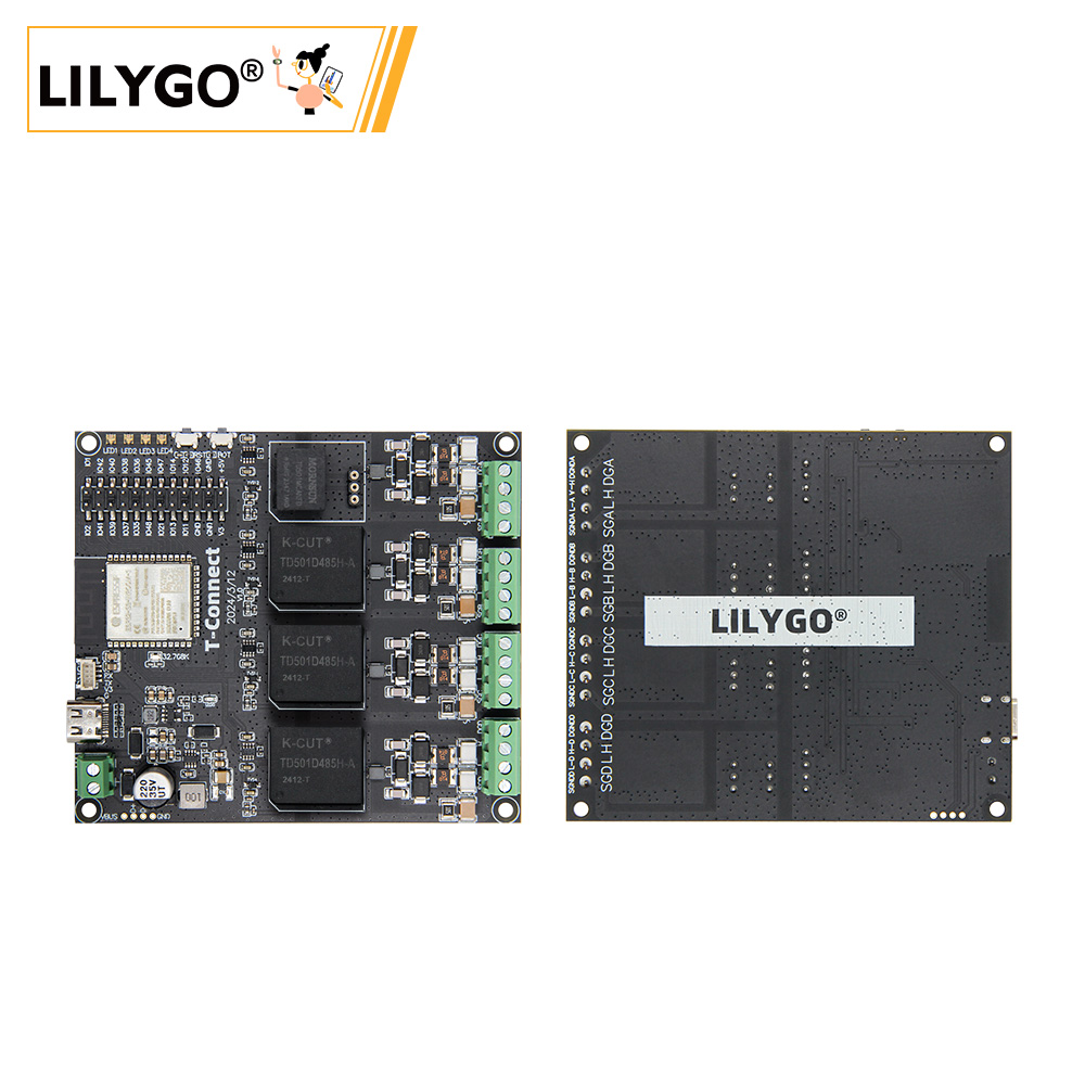
T-Connect is an industrial-grade multi-protocol communication board based on ESP32-S3-R8 (16 MB Flash, 8 MB PSRAM). Integrates up to three independent RS485 channels and one CAN bus channel, APA102 LED strip controller, 10 A relay, and QWIIC expansion interface. Supports switching between CAN and RS485 modules. 7–12 V DC wide-range input. 94 × 83 × 13 mm. Suitable for IoT gateways, industrial automation, and smart lighting scenarios.
Quick Start
Example Support
| Example | PlatformIO/Arduino | ESP-IDF | Description |
|---|---|---|---|
| Original_Test | ✓ | Factory test program | |
| APA102_Blink | ✓ | APA102 LED blink example | |
| CAN | ✓ | CAN bus communication | |
| RS485 | ✓ | RS485 communication |
PlatformIO
- Install Visual Studio Code and Python
- Search for and install the PlatformIO IDE extension in VS Code
- Clone the T-Connect repository
- Open
platformio.iniand under[platformio]uncomment the desired environment - Click ✓ to compile, click → to upload
Arduino
- Install Arduino IDE
- Add ESP32 boards URL:
https://raw.githubusercontent.com/espressif/arduino-esp32/gh-pages/package_esp32_index.json - Copy the project
librariesfolder to your Arduino libraries folder - In Tools → Board, configure:
| Arduino IDE Setting | Value |
|---|---|
| Board | ESP32S3 Dev Module |
| Upload Speed | 921600 |
| USB Mode | Hardware CDC and JTAG |
| USB CDC On Boot | Enabled |
| USB Firmware MSC On Boot | Disabled |
| USB DFU On Boot | Disabled |
| CPU Frequency | 240 MHz (WiFi) |
| Flash Mode | QIO 80 MHz |
| Flash Size | 16MB (128Mb) |
| Core Debug Level | None |
| Partition Scheme | 16M Flash (3MB APP/9.9MB FATFS) |
| PSRAM | OPI PSRAM |
| Arduino Runs On | Core 1 |
| Events Run On | Core 1 |
- Click Upload
Development Platforms
Video
Key Features
- ESP32-S3-R8 dual-core LX7 @ 240 MHz, 16 MB Flash, 8 MB PSRAM, Wi-Fi + BT 5.0
- Up to 3 × RS485 + 1 × CAN bus, switchable configuration
- APA102 RGB LED strip controller
- 10 A relay output
- 7–12 V DC input, 4 × mounting holes, 94 × 83 × 13 mm
Product Parameters
| Feature | Specification |
|---|---|
| MCU | ESP32-S3-R8 |
| Flash | 16 MB |
| PSRAM | 8 MB (Octal SPI) |
| Communication | RS485 (up to 3 ch) + CAN (TWAI) |
| LED Driver | APA102 |
| Relay | 10 A output |
| Wi-Fi | 2.4 GHz 802.11 b/g/n |
| Bluetooth | Bluetooth 5.0 LE |
| USB | 1 × Type-C (USB + OTG) |
| Power Input | 7–12 V DC or 5 V/500 mA USB |
| Expansion | 1 × QWIIC |
| Buttons | RESET + BOOT |
| Mounting Holes | 4 × 2 mm |
| Dimensions | 94 × 83 × 13 mm |
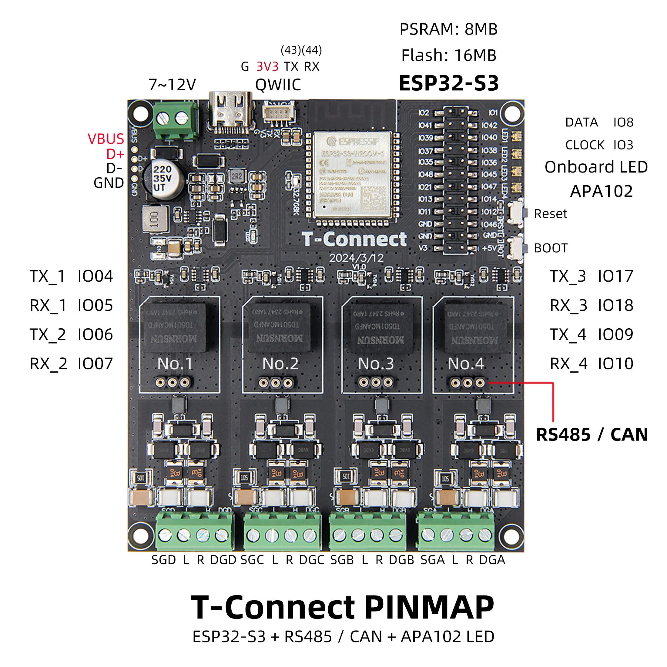
Pin Diagram
Pin Mapping
| APA102 | IO8 (DATA), IO3 (CLOCK) |
|---|---|
| CAN/RS485 TX_1/RX_1 | IO4, IO5 |
| CAN/RS485 TX_2/RX_2 | IO6, IO7 |
| CAN/RS485 TX_3/RX_3 | IO17, IO18 |
| CAN/RS485 TX_4/RX_4 | IO9, IO10 |
Dimension Diagram
Schematic
Datasheet
Software Development
Dependent Libraries
FAQ
Q. Why does my board keep failing to upload programs? A. Hold down the BOOT button and try uploading again.
Q. How to configure switching between RS485 and CAN modules? A. Switching is achieved through onboard configuration jumpers or software settings. Refer to the schematic and example code.
Q. Why is there no serial data output from the Uart interface? A. The project defaults to USB CDC as Uart0. Set USB CDC On Boot to Disabled in Arduino Tools, or change
-DARDUINO_USB_CDC_ON_BOOT=truetofalseinplatformio.ini.
Version History
| Version | Release Date | Update Description |
|---|---|---|
| T-Connect V1.0 | — | Initial version |