T-Deck Plus get it now
Overview
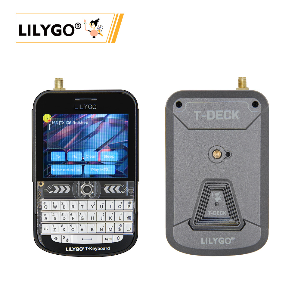
LILYGO T-Deck Plus is a highly integrated multi-functional embedded development platform based on the ESP32-S3 chip. It integrates a 2.8-inch ST7789 LCD (320 × 240), trackball navigation module, physical keyboard (I²C), TF card, LoRa SX1262 wireless module, and ES7210 microphone array. Compared to the standard T-Deck, T-Deck Plus adds a GPS module (MIA-M10Q) with the Grove interface pins repurposed for GPS — the Grove interface is not available as a general-purpose connector on T-Deck Plus.
Notes:
- The Grove interface pins on T-Deck Plus are allocated to the GPS module and cannot be used as a general-purpose interface.
- T-Deck updated the TFT_eSPI ST7789 initialization sequence on 2024-07-26. If screen display is incorrect, check whether the initialization sequence in the repo matches.
- The LoRa radio module shares the SPI bus with other peripherals. Only one SPI device can be selected at a time — ensure all other SPI device CS lines are high (inactive) before communicating with the SX1262.
- When powered by battery, GPIO10 must be set HIGH. This requirement can be ignored when the board is powered via USB.
Quick Start
Example Support
| Example | PlatformIO/Arduino | ESP-IDF | Description |
|---|---|---|---|
| T-Deck Examples | ✓ | Keyboard, Microphone, GPS, Touchpad, Unit Test |
examples
├─Keyboard_ESP32C3       # ESP32C3 keyboard I2C slave
├─Keyboard_T_Deck_Master # T-Deck read from keyboard
├─Microphone             # Noise detection
├─Touchpad               # Read touch coordinates
├─GPSShield              # GPS Shield example
└─UnitTest               # Factory hardware unit testing
If microphone is enabled, the middle trackball button (GPIO0) is not available.
PlatformIO
- Install Visual Studio Code and Python
- Search for and install the PlatformIO IDE extension in VS Code
- After restarting VS Code, click File → Open Folder → select the
T-Deckdirectory - Open
platformio.ini, uncomment the example line you want to use (only one active at a time) - Click ✓ to compile, connect via USB, click → to upload
Arduino
- Install Arduino IDE
- Copy all folders from
T-Deck/libto your Arduino libraries folder - In Tools → Board, configure:
| Arduino IDE Setting | Value |
|---|---|
| Board | ESP32S3 Dev Module |
| USB CDC On Boot | Enable |
| CPU Frequency | 240 MHz |
| USB DFU On Boot | Disable |
| Flash Mode | QIO 80 MHz |
| Flash Size | 16MB(128Mb) |
| USB Firmware MSC On Boot | Disable |
| PSRAM | OPI PSRAM |
| Partition Scheme | 16M Flash(3MB APP/9.9MB FATFS) |
| USB Mode | Hardware CDC and JTAG |
| Upload Mode | UART0/Hardware CDC |
| Upload Speed | 921600 |
- Click Upload. If upload fails, hold the trackball BOOT button, insert USB, then click Upload. Press RST to exit download mode.
The ESP32C3 programming interface is the 6-pin header near the RST button (top to bottom: 3V3, GND, RST, BOOT, RX, TX).
Development Platforms
Video
Key Features
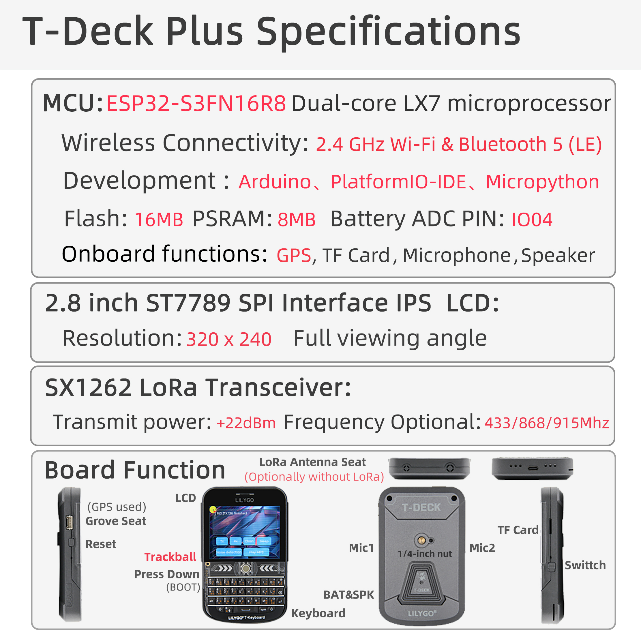
- ESP32-S3FN16R8 dual-core LX7 @ 240 MHz, Wi-Fi + Bluetooth 5.0 LE
- SX1262 LoRa (433–915 MHz, optional)
- MIA-M10Q GNSS module (GPS, added vs. standard T-Deck)
- 2.8-inch ST7789 LCD (320 × 240), trackball navigation (no touch screen)
- Physical keyboard (I²C)
- ES7210 audio codec + MSM381A3729H9CP microphone array
- 2000 mAh lithium polymer battery
- 16 MB Flash + 8 MB PSRAM + TF card slot
Product Parameters
| Feature | Specification |
|---|---|
| MCU | ESP32-S3FN16R8 @ Dual-core LX7, 240 MHz |
| Flash | 16 MB |
| PSRAM | 8 MB |
| Wi-Fi | 2.4 GHz 802.11 b/g/n |
| Bluetooth | Bluetooth 5.0 LE |
| LoRa | SX1262, 433–915 MHz (optional) |
| GPS | MIA-M10Q GNSS |
| Display | 2.8-inch ST7789 LCD, 320 × 240 |
| Input | Trackball + physical keyboard (I²C) |
| Audio | ES7210 codec + microphone array |
| Battery | 2000 mAh lithium polymer |
| Storage | TF card expansion |
| USB | 1 × Type-C |
| Dimensions | 100 × 68 × 11 mm |
Pin Diagram
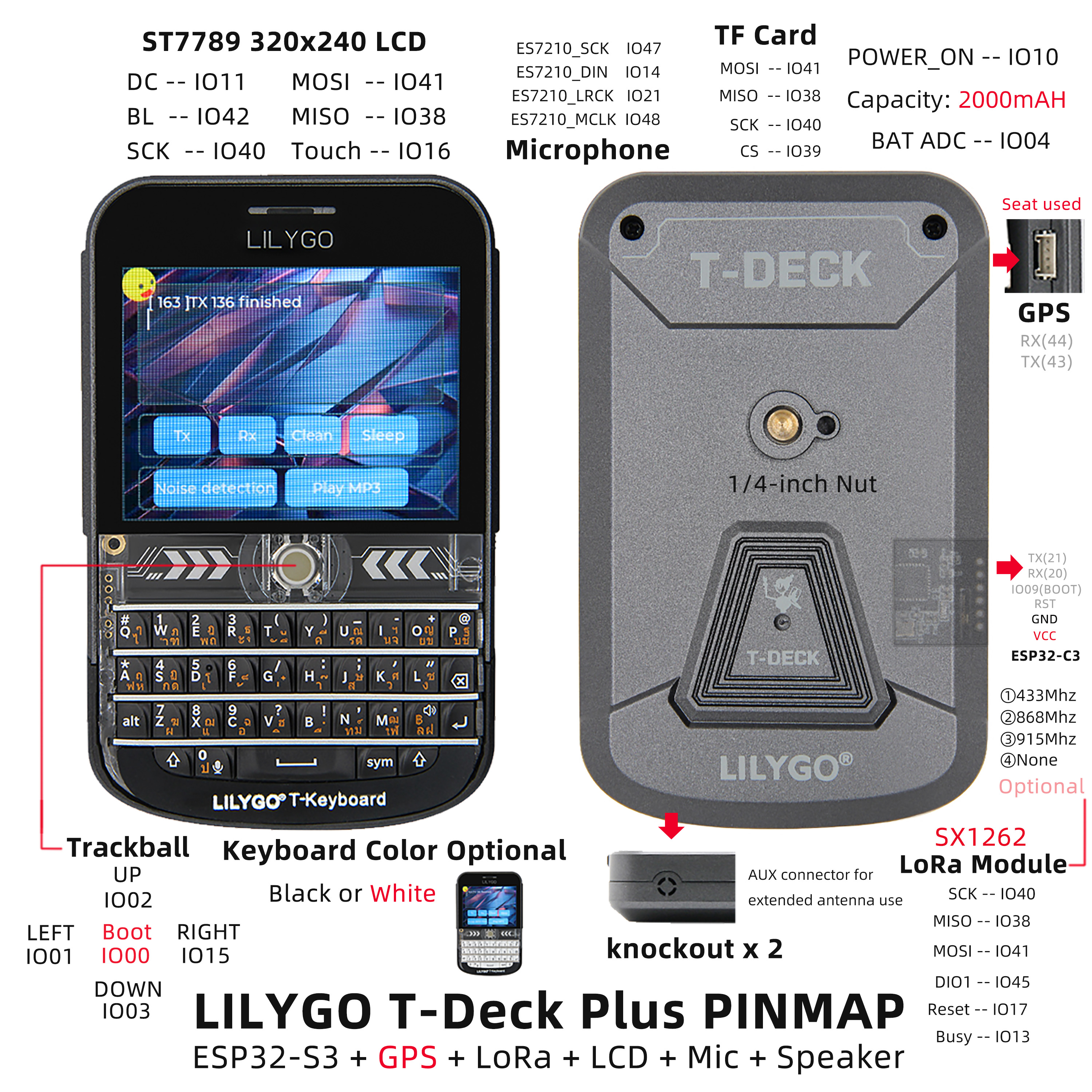
Pin Mapping
| Signal | GPIO |
|---|---|
| Power Enable | 10 |
| I2S WS | 5 |
| I2S BCK | 7 |
| I2S DOUT | 6 |
| I2C SDA | 18 |
| I2C SCL | 8 |
| Battery ADC | 4 |
| Touch INT | 16 |
| Keyboard INT | 46 |
| SD CS | 39 |
| TFT CS | 12 |
| LoRa CS | 9 |
| TFT DC | 11 |
| TFT Backlight | 42 |
| SPI MOSI | 41 |
| SPI MISO | 38 |
| SPI SCK | 40 |
| Trackball G01 | 3 |
| Trackball G02 | 2 |
| Trackball G03 | 15 |
| Trackball G04 | 1 |
| ES7210 MCLK | 48 |
| ES7210 LRCK | 21 |
| ES7210 SCK | 47 |
| ES7210 DIN | 14 |
| LoRa BUSY | 13 |
| LoRa RST | 17 |
| LoRa DIO1 | 45 |
| BOOT | 0 |
| GPS TX | 43 |
| GPS RX | 44 |
Peripheral Initialization
The following snippets show the minimum setup for each peripheral using the pin definitions above. Copy the #define block from Pin Mapping into your sketch, then use the relevant snippet.
Before any SPI transaction — pull all other CS lines HIGH first:
cppdigitalWrite(BOARD_SDCARD_CS, HIGH); digitalWrite(BOARD_TFT_CS, HIGH); digitalWrite(RADIO_CS_PIN, HIGH);
Power Enable (battery-powered builds)
// Must be set HIGH when running on battery; safe to call on USB too.
pinMode(BOARD_POWERON, OUTPUT);
digitalWrite(BOARD_POWERON, HIGH);
Display (ST7789 — Arduino_GFX)
#include <Arduino_GFX_Library.h>

Arduino_DataBus *bus = new Arduino_ESP32SPI(
    BOARD_TFT_DC, BOARD_TFT_CS,
    BOARD_SPI_SCK, BOARD_SPI_MOSI, BOARD_SPI_MISO);

Arduino_GFX *gfx = new Arduino_ST7789(bus, -1, 0, true, 320, 240);

void setup() {
    pinMode(BOARD_TFT_BACKLIGHT, OUTPUT);
    digitalWrite(BOARD_TFT_BACKLIGHT, HIGH);
    gfx->begin();
    gfx->fillScreen(BLACK);
}
Display (ST7789 — TFT_eSPI)
Requires
User_Setup.hconfigured for T-Deck — see the 2024-07-26 commit for the correct initialization sequence.
#include <TFT_eSPI.h>

TFT_eSPI tft;

void setup() {
    pinMode(BOARD_TFT_BACKLIGHT, OUTPUT);
    digitalWrite(BOARD_TFT_BACKLIGHT, HIGH);
    tft.init();
    tft.setRotation(1);
    tft.fillScreen(TFT_BLACK);
}
LoRa (SX1262 — RadioLib)
#include <RadioLib.h>

SX1262 radio = new Module(
    RADIO_CS_PIN,   // CS
    RADIO_DIO1_PIN, // DIO1 / IRQ
    RADIO_RST_PIN,  // RST
    RADIO_BUSY_PIN  // BUSY
);

void setup() {
    pinMode(BOARD_SDCARD_CS, OUTPUT); digitalWrite(BOARD_SDCARD_CS, HIGH);
    pinMode(BOARD_TFT_CS,    OUTPUT); digitalWrite(BOARD_TFT_CS,    HIGH);

    SPI.begin(BOARD_SPI_SCK, BOARD_SPI_MISO, BOARD_SPI_MOSI);

    int state = radio.begin(915.0);
    if (state != RADIOLIB_ERR_NONE) {
        Serial.printf("LoRa init failed: %d\n", state);
    }
}
GPS (MIA-M10Q — TinyGPSPlus)
T-Deck Plus only. The Grove interface pins are repurposed for GPS — Grove cannot be used as a general-purpose connector.
#include <TinyGPSPlus.h>

TinyGPSPlus gps;

void setup() {
    // GPS communicates over UART (Serial1 on ESP32-S3)
    Serial1.begin(9600, SERIAL_8N1, BOARD_GPS_TX_PIN, BOARD_GPS_RX_PIN);
}

void loop() {
    while (Serial1.available()) {
        gps.encode(Serial1.read());
    }
    if (gps.location.isUpdated()) {
        Serial.printf("Lat: %.6f  Lng: %.6f\n",
            gps.location.lat(), gps.location.lng());
    }
}
Keyboard (I²C)
#include <Wire.h>

#define KEYBOARD_ADDR 0x55

void setup() {
    Wire.begin(BOARD_I2C_SDA, BOARD_I2C_SCL);
    pinMode(BOARD_KEYBOARD_INT, INPUT_PULLUP);
}

void loop() {
    if (digitalRead(BOARD_KEYBOARD_INT) == LOW) {
        Wire.requestFrom(KEYBOARD_ADDR, 1);
        if (Wire.available()) {
            char key = Wire.read();
            Serial.printf("Key: %c\n", key);
        }
    }
}
Trackball
void setup() {
    pinMode(BOARD_TBOX_G01, INPUT);
    pinMode(BOARD_TBOX_G02, INPUT);
    pinMode(BOARD_TBOX_G03, INPUT);
    pinMode(BOARD_TBOX_G04, INPUT);
}
Microphone (ES7210 — I²S)
When the microphone is enabled, GPIO0 (BOOT / trackball center button) is not available.
#include <driver/i2s.h>

void setup() {
    i2s_config_t i2s_config = {
        .mode = (i2s_mode_t)(I2S_MODE_MASTER | I2S_MODE_RX),
        .sample_rate = 16000,
        .bits_per_sample = I2S_BITS_PER_SAMPLE_16BIT,
        .channel_format = I2S_CHANNEL_FMT_RIGHT_LEFT,
        .communication_format = I2S_COMM_FORMAT_STAND_I2S,
        .intr_alloc_flags = ESP_INTR_FLAG_LEVEL1,
        .dma_buf_count = 4,
        .dma_buf_len = 256,
        .use_apll = false,
    };
    i2s_pin_config_t pin_config = {
        .mck_io_num   = BOARD_ES7210_MCLK,
        .bck_io_num   = BOARD_ES7210_SCK,
        .ws_io_num    = BOARD_ES7210_LRCK,
        .data_in_num  = BOARD_ES7210_DIN,
        .data_out_num = I2S_PIN_NO_CHANGE,
    };
    i2s_driver_install(I2S_NUM_0, &i2s_config, 0, NULL);
    i2s_set_pin(I2S_NUM_0, &pin_config);
}
SD Card (SPI)
#include <SD.h>

void setup() {
    SPI.begin(BOARD_SPI_SCK, BOARD_SPI_MISO, BOARD_SPI_MOSI);
    if (!SD.begin(BOARD_SDCARD_CS)) {
        Serial.println("SD init failed");
    }
}
Dimension Diagram
Schematic
Datasheet
Software Development
Dependent Libraries
FAQ
Q. Can the Grove interface on T-Deck Plus be used? A. No. On T-Deck Plus, the Grove interface pins are allocated to the GPS module and cannot be used as a general-purpose interface.
Q. Does T-Deck Plus have a touch screen? A. No. It uses a trackball navigation module instead.
Q. Upload keeps failing? A. Hold the trackball center button (BOOT), insert USB, then click Upload. Press RST to exit download mode.
Q. Arduino IDE prompts to upgrade libraries — should I? A. Do not upgrade. Stay with the library versions in the
libdirectory.
Version History
| Version | Release Date | Update Description |
|---|---|---|
| V1.0 | — | Initial release |