T3-S3 get it now
Overview
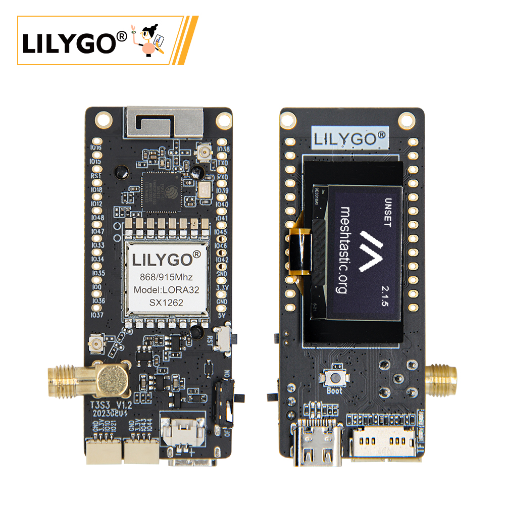
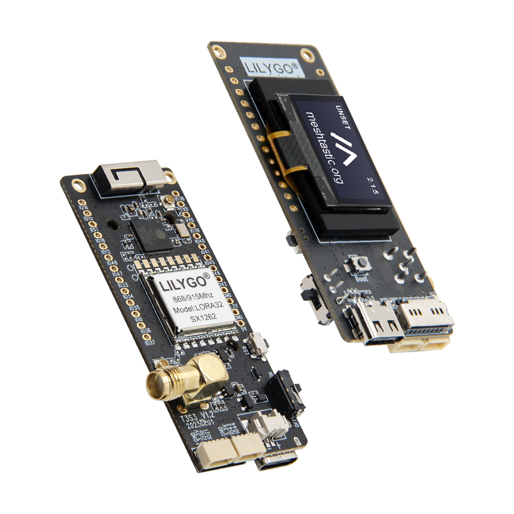
T3-S3 (LILYGO T3-S3 V1.2) is a compact development board integrating the ESP32-S3FH4R2 microcontroller with multi-band LoRa communication. It can be optionally configured with SX1262/SX1276/SX1278 (433/868/915 MHz) or SX1280 (2.4 GHz) LoRa modules, supporting long-distance low-power communication. Features an onboard 0.96-inch SSD1306 OLED (128 × 64) and MicroSD (TF) card slot. Power supply and programming via Type-C USB. Suitable for IoT sensor networks, environmental monitoring, and other low-power applications.
Quick Start
Example Support
| Example | PlatformIO/Arduino | ESP-IDF | Description |
|---|---|---|---|
| LilyGo-LoRa-Series | ✓ | LoRa, OLED, SD Card, LoRaWAN examples |
Available examples
./examples/
├── ArduinoLoRa          # SX1276/SX1278 only
├── GPS                  # T-Beam GPS examples
├── LoRaWAN              # LMIC_Library_OTTA, RadioLib_OTAA
├── OLED                 # SSD1306/SH1106 display examples
├── RadioLibExamples     # SX1276/78/62/80 Transmit/Receive
├── T3S3Factory          # T3-S3 factory test
└── Factory              # Factory test examples
PlatformIO
- Install Visual Studio Code and Python
- Search for and install the PlatformIO IDE extension in VS Code
- Open the
LilyGo-LoRa-Seriesproject folder - Open
platformio.ini, underdefault_envsuncomment your board name - Click ✓ to compile, connect via USB-C, click → to upload
Arduino
- Install Arduino IDE
- Install Arduino ESP32
- Copy all folders from the
libdirectory to your Arduino libraries folder:- Windows:
C:\Users\{Username}\Documents\Arduino - macOS:
/Users/{Username}/Documents/Arduino - Linux:
/home/{Username}/Arduino
- Windows:
- Open the example
.inofile from theexamplesdirectory - In Tools → Board, configure:
| Arduino IDE Setting | Value |
|---|---|
| Board | LilyGo T3-S3 |
| Port | Your port |
| USB CDC On Boot | Enable |
| CPU Frequency | 240 MHz (WiFi) |
| Core Debug Level | None |
| USB DFU On Boot | Disable |
| Erase All Flash Before Sketch Upload | Disable |
| Events Run On | Core1 |
| Arduino Runs On | Core1 |
| USB Firmware MSC On Boot | Disable |
| Partition Scheme | Default 4MB with spiffs (1.2MB APP/1.5MB SPIFFS) |
| PSRAM | QSPI PSRAM |
| Board Revision | Select per your actual model |
| Upload Mode | UART0/Hardware CDC |
| Upload Speed | 921600 |
| USB Mode | CDC and JTAG |
| Programmer | Esptool |
- Click Upload
If upload fails: hold BOOT, press RST, release RST, then click Upload.
Development Platforms
Video
Key Features
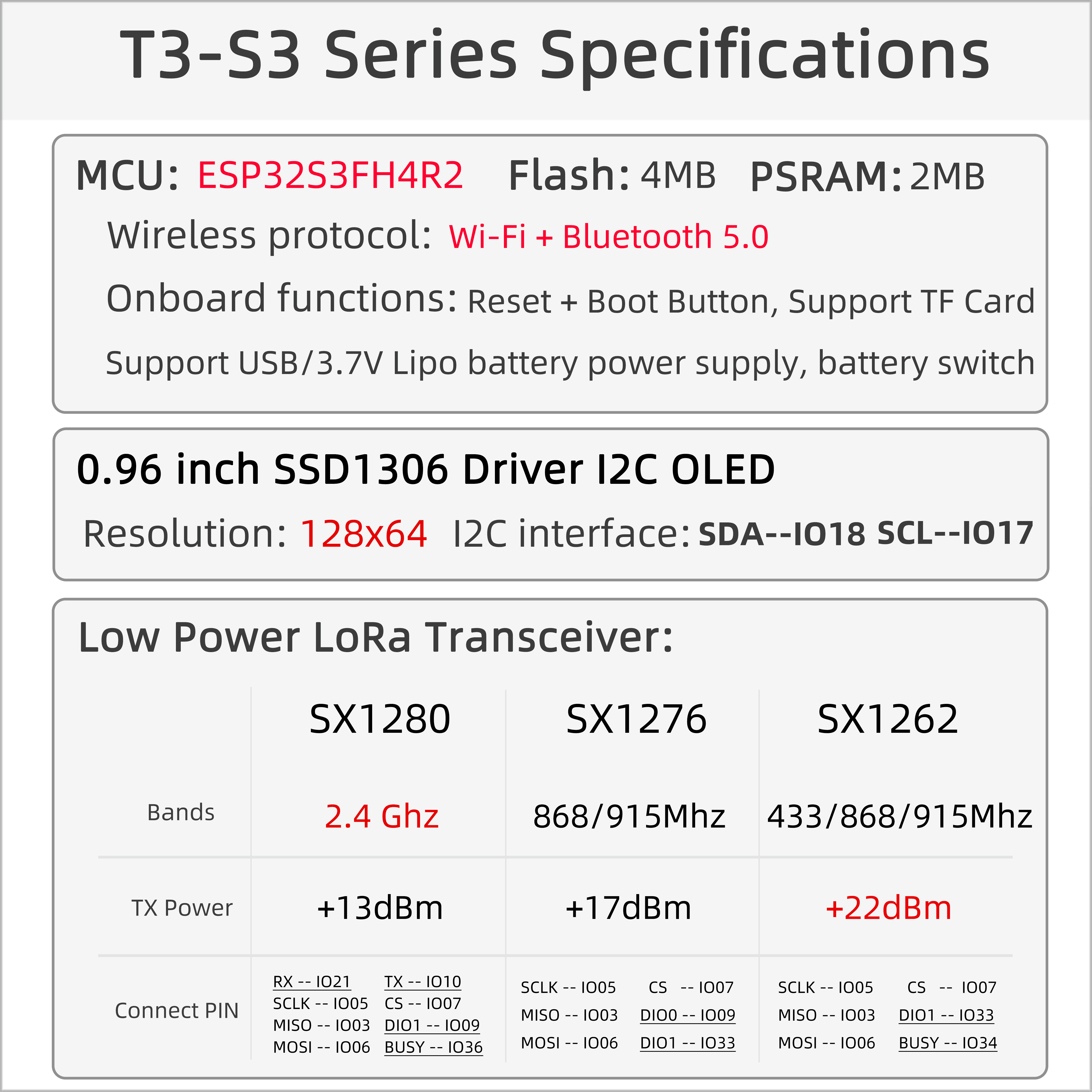
- ESP32-S3FH4R2 dual-core LX7 @ 240 MHz, Wi-Fi + Bluetooth 5.0
- SX1262 / SX1276 / SX1278 (433/868/915 MHz) or SX1280 (2.4 GHz) — optional
- 0.96-inch SSD1306 OLED (128 × 64), I2C
- 4 MB Flash + 2 MB QSPI PSRAM + TF card slot
- USB-C power and programming
- 2 × QWIIC interfaces, 2.54mm 2×13 GPIO expansion
Product Parameters
| Feature | Specification |
|---|---|
| MCU | ESP32-S3FH4R2 @ Dual-core LX7, 240 MHz |
| Flash | 4 MB (Quad-SPI) |
| PSRAM | 2 MB (Quad-SPI) |
| Wi-Fi | 2.4 GHz 802.11 b/g/n |
| Bluetooth | Bluetooth 5.0 |
| LoRa | SX1262 / SX1276 / SX1278 (433/868/915 MHz) or SX1280 (2.4 GHz) |
| Display | 0.96-inch SSD1306 OLED, 128 × 64, I2C |
| Storage | TF card slot (SPI) |
| USB | 1 × Type-C |
| Expansion | 2 × QWIIC, 2.54mm 2×13 GPIO |
| Buttons | RESET + BOOT |
| Mounting Holes | 2 × M2 |
| Dimensions | 66 × 36 × 14 mm |
Pin Diagram
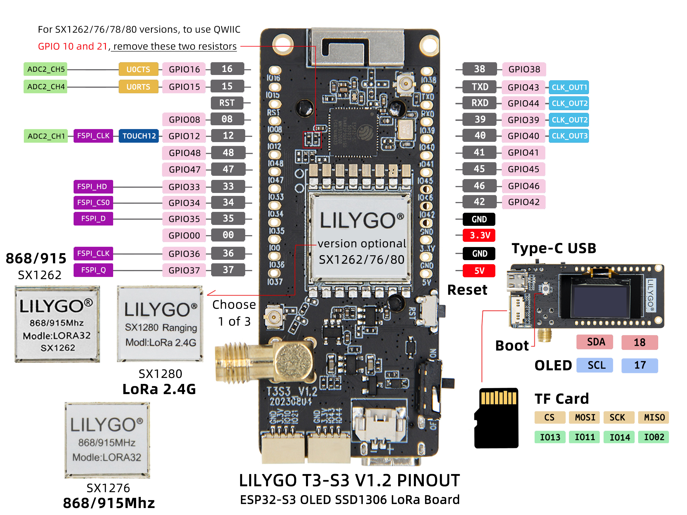
SX1262 Pin Mapping
| Signal | GPIO | Available |
|---|---|---|
| QWIIC Uart1 TX | 43 | ✅ |
| QWIIC Uart1 RX | 44 | ✅ |
| QWIIC IO10 | 10 | ✅ |
| QWIIC IO21 | 21 | ✅ |
| I2C SDA | 18 | ❌ |
| I2C SCL | 17 | ❌ |
| SD CS | 13 | ❌ |
| SD MOSI | 11 | ❌ |
| SD MISO | 2 | ❌ |
| SD SCK | 14 | ❌ |
| LoRa SCK | 5 | ❌ |
| LoRa MISO | 3 | ❌ |
| LoRa MOSI | 6 | ❌ |
| LoRa RESET | 8 | ❌ |
| LoRa DIO1 | 33 | ❌ |
| LoRa BUSY | 34 | ❌ |
| LoRa CS | 7 | ❌ |
| BOOT Button | 0 | ❌ |
| Battery ADC | 1 | ❌ |
| Onboard LED | 37 | ❌ |
SX1276 / SX1278 Pin Mapping
| Signal | GPIO | Available |
|---|---|---|
| QWIIC Uart1 TX | 43 | ✅ |
| QWIIC Uart1 RX | 44 | ✅ |
| QWIIC IO10 | 10 | ✅ |
| QWIIC IO21 | 21 | ✅ |
| I2C SDA | 18 | ❌ |
| I2C SCL | 17 | ❌ |
| SD CS | 13 | ❌ |
| SD MOSI | 11 | ❌ |
| SD MISO | 2 | ❌ |
| SD SCK | 14 | ❌ |
| LoRa SCK | 5 | ❌ |
| LoRa MISO | 3 | ❌ |
| LoRa MOSI | 6 | ❌ |
| LoRa RESET | 8 | ❌ |
| LoRa DIO0 | 9 | ❌ |
| LoRa DIO1 | 33 | ❌ |
| LoRa DIO2 | 34 | ❌ |
| LoRa DIO3 | 21 | ❌ |
| LoRa DIO4 | 10 | ❌ |
| LoRa DIO5 | 36 | ❌ |
| LoRa CS | 7 | ❌ |
| BOOT Button | 0 | ❌ |
| Battery ADC | 1 | ❌ |
| Onboard LED | 37 | ❌ |
GPIO10 and GPIO21 can be freed by removing the two resistors connecting them to LoRa DIO3/DIO4.
SX1280 Pin Mapping
| Signal | GPIO | Available |
|---|---|---|
| QWIIC Uart1 TX | 43 | ✅ |
| QWIIC Uart1 RX | 44 | ✅ |
| I2C SDA | 18 | ❌ |
| I2C SCL | 17 | ❌ |
| SD CS | 13 | ❌ |
| SD MOSI | 11 | ❌ |
| SD MISO | 2 | ❌ |
| SD SCK | 14 | ❌ |
| LoRa SCK | 5 | ❌ |
| LoRa MISO | 3 | ❌ |
| LoRa MOSI | 6 | ❌ |
| LoRa RESET | 8 | ❌ |
| LoRa DIO1 | 9 | ❌ |
| LoRa BUSY | 36 | ❌ |
| LoRa CS | 7 | ❌ |
| BOOT Button | 0 | ❌ |
| Battery ADC | 1 | ❌ |
| Onboard LED | 37 | ❌ |
Dimension Diagram
Schematic
Datasheet
Software Development
Dependent Libraries
FAQ
Q. How to choose LoRa module version? A. SX1262/SX1276 are suitable for Sub-1GHz bands (433/868/915 MHz) with longer communication distance; SX1280 is suitable for the 2.4 GHz band with higher data rate.
Q. OLED screen not displaying? A. Check the I2C address configuration (SSD1306 default is 0x3C). Confirm SDA = GPIO18, SCL = GPIO17.
Q. SD card not recognized? A. Ensure the SD card is formatted as FAT32, check that it is properly inserted, and try a different card.
Q. Upload fails? A. Hold BOOT, press and release RST, then click Upload.
Version History
| Version | Release Date | Update Description |
|---|---|---|
| T3S3_V1.2 | — | Initial version: ESP32-S3 with multi-band LoRa |
| T3S3_V1.3 | — | Hardware optimization update |