
T-Dongle-S3 get it now
Overview
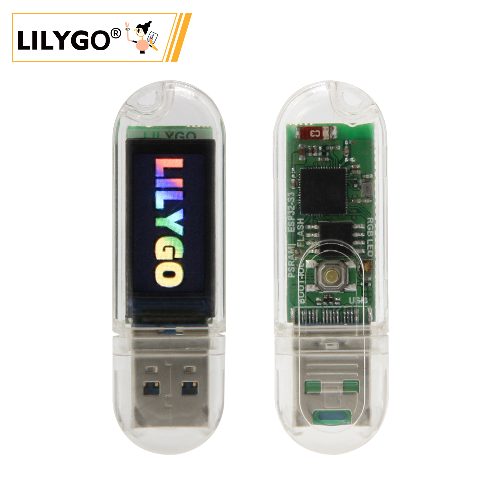
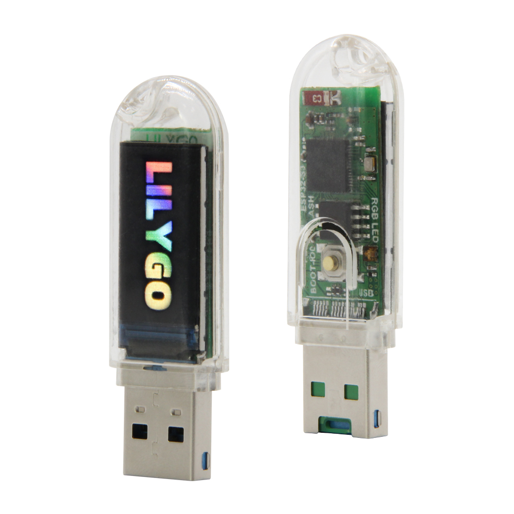
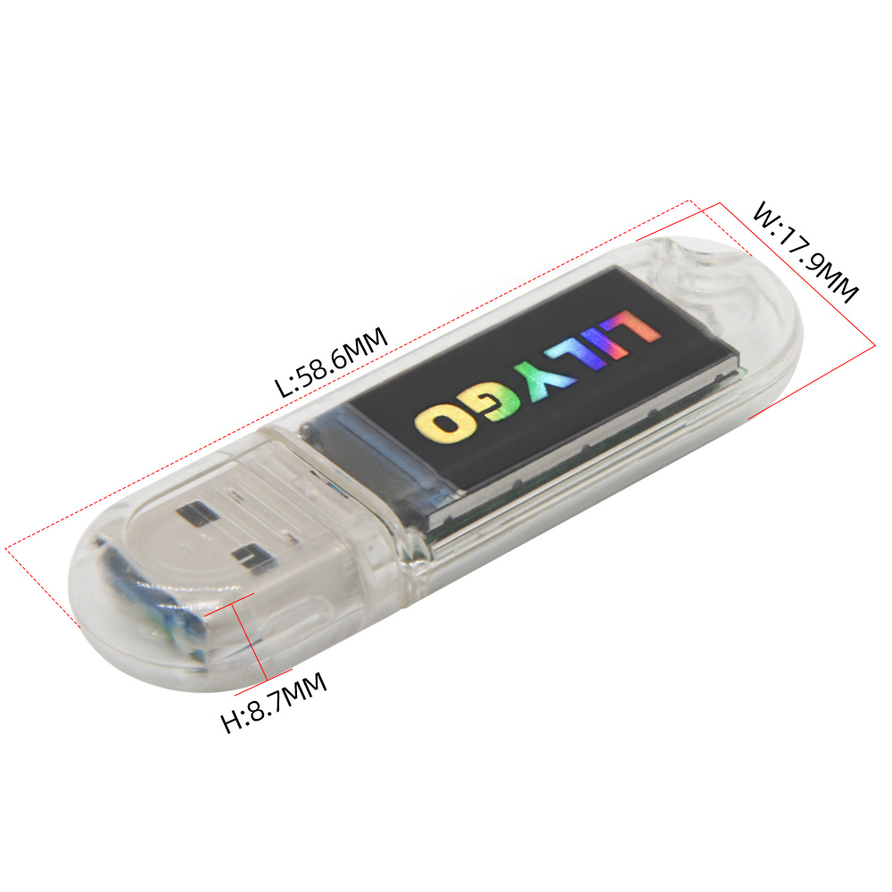
LILYGO T-Dongle-S3 is an ESP32-S3 USB dongle development board in a USB Type-A plug form factor, suitable for USB gadgets, portable displays, data logging, and IoT education projects. It uses the ESP32-S3 with 16MB Quad-SPI Flash and 512KB SRAM, and has no PSRAM. Onboard peripherals include a 0.96-inch ST7735 SPI color display (160 × 80), APA102 RGB LED, TF card slot, BOOT button, and QWIIC connector.
Quick Start
Example Support
| Example | PlatformIO/Arduino | ESP-IDF | Description |
|---|---|---|---|
| T-Dongle-S3 | ✓ | Display, TF card, LED, QWIIC examples |
PlatformIO
- Install Visual Studio Code and Python
- Search for and install the PlatformIO IDE extension in VS Code, then restart VS Code
- Open the
T-Dongle-S3project folder - Enable
default_envs = T-Dongle-S3inplatformio.ini - Keep only one valid
src_dir = xxxxexample path - Click ✓ to build, plug in the device, then click → to upload
Arduino
- Install Arduino IDE
- Install Arduino ESP32 Core 3.3.0 or later
- Copy all folders in the project
libdirectory to the Arduino Sketchbook libraries directory - In Tools → Board, configure:
| Arduino IDE Setting | Value |
|---|---|
| Board | ESP32S3 Dev Module |
| Port | Your port |
| USB CDC On Boot | Enable |
| CPU Frequency | 240MHz (WiFi) |
| Core Debug Level | None |
| USB DFU On Boot | Disable |
| Erase All Flash Before Sketch Upload | Disable |
| Flash Mode | QIO 80MHz |
| Flash Size | 16MB (128Mb) |
| Arduino Runs On | Core1 |
| USB Firmware MSC On Boot | Disable |
| Partition Scheme | 16M Flash (3MB APP/9.9MB FATFS) |
| PSRAM | Disabled |
| Upload Speed | 921600 |
| Programmer | Esptool |
| USB Mode | Hardware CDC and JTAG |
Note: For examples with USB in the name, set USB Mode to USB-OTG (TinyUSB). If upload fails, hold the BOOT button while plugging the T-Dongle-S3 into the computer USB port to enter download mode.
Related Videos
Key Features
- ESP32-S3, Wi-Fi 802.11 b/g/n + Bluetooth 5 LE
- 16MB Quad-SPI Flash, 512KB SRAM, no PSRAM
- USB Type-A dongle form factor
- 0.96-inch ST7735 SPI color display, 160 × 80 resolution
- APA102 RGB LED, BGR color order
- TF card slot using SDMMC pins
- QWIIC connector configured for serial port function by default
- BOOT button for custom functions or download mode
Specifications
| Parameter | Value |
|---|---|
| SOC | ESP32-S3 |
| Flash | 16MB (Quad-SPI) |
| SRAM | 512KB |
| PSRAM | No PSRAM |
| Wireless | Wi-Fi 802.11 b/g/n, Bluetooth 5 LE |
| Display | 0.96-inch ST7735 (SPI), 160 × 80 |
| RGB LED | APA102 × 1, BGR |
| Storage | TF card slot |
| USB Input Voltage | 4.8V ~ 5.5V |
| USB Max Current | 800mA |
| USB | USB Type-A plug |
| QWIIC | Serial port function by default; add external pull-up resistors for I2C |
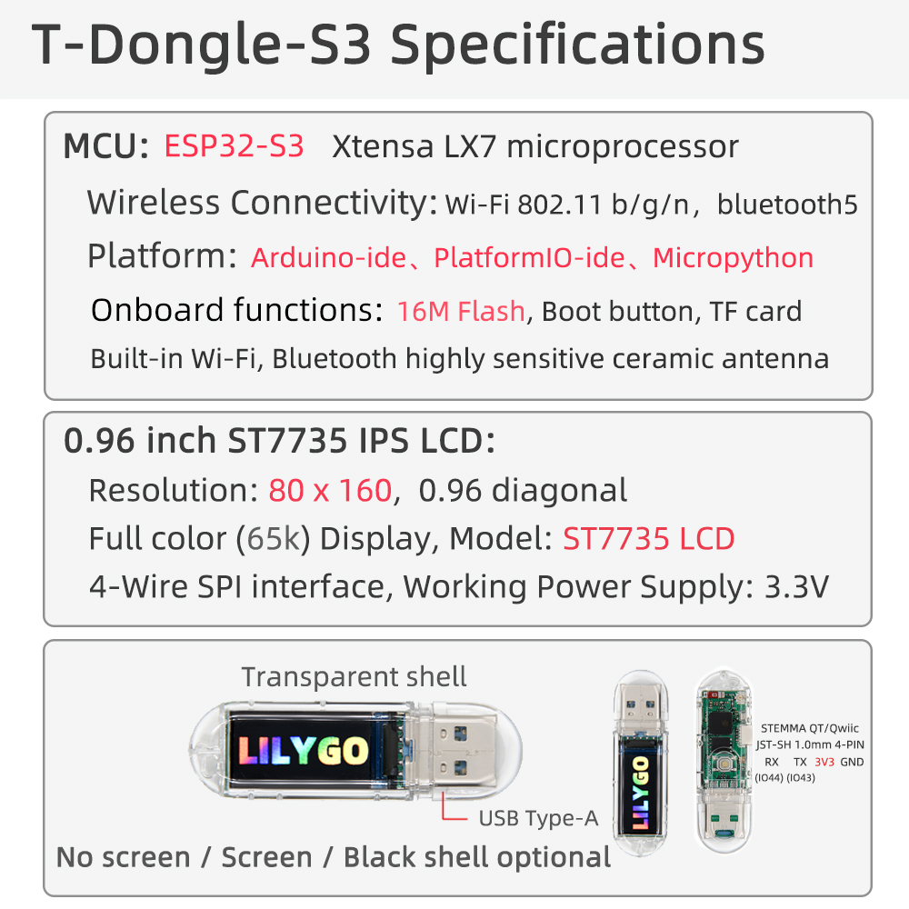
Pin Diagram
| Name | GPIO |
|---|---|
| RGB DIN | GPIO40 |
| RGB CLK | GPIO39 |
| SDMMC D0 | GPIO14 |
| SDMMC D1 | GPIO17 |
| SDMMC D2 | GPIO21 |
| SDMMC D3 | GPIO18 |
| SDMMC CLK | GPIO12 |
| SDMMC CMD | GPIO16 |
| Button | GPIO0 |
| QWIIC TX | GPIO43 |
| QWIIC RX | GPIO44 |
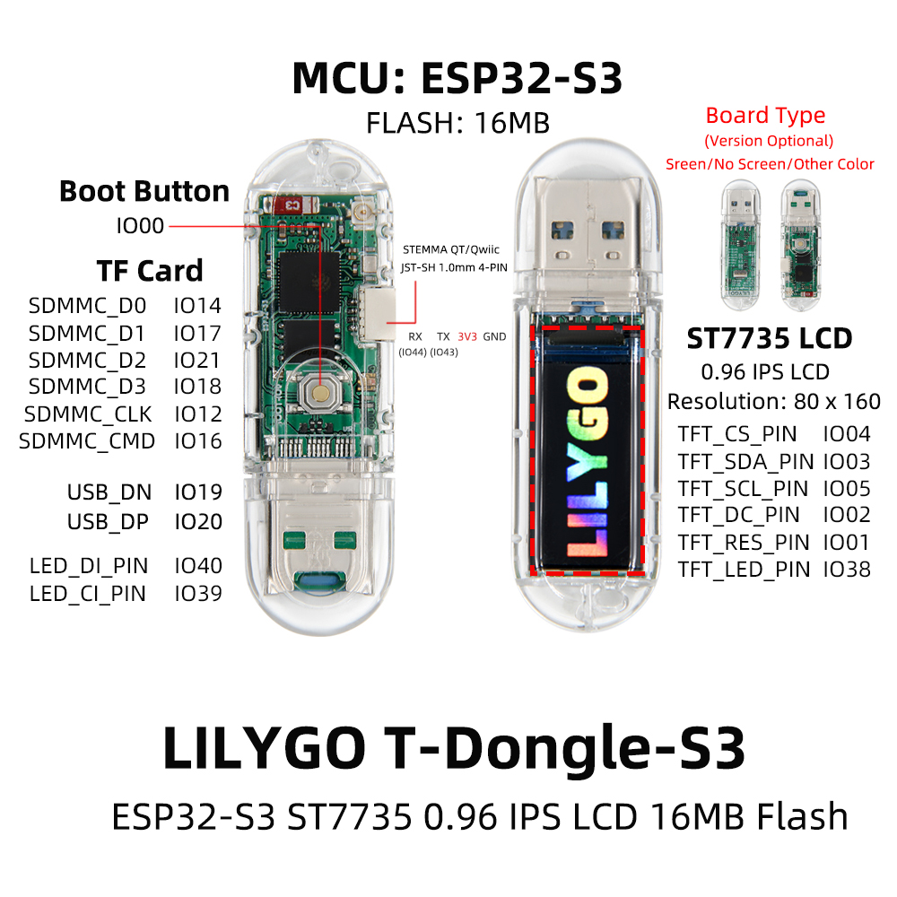
QWIIC Connector
The QWIIC connector is configured for serial port function by default. To use it for I2C, add pull-up resistors to the external sensor.
Dimensions
Schematic
Datasheet
Software Libraries
FAQ
Q. Upload keeps failing?
A. Hold the BOOT button while plugging the T-Dongle-S3 into the computer USB port to enter download mode. After flashing, unplug and power it again. Do not hold BOOT while powering on for normal startup.Q. Can QWIIC be used as I2C directly?
A. QWIIC is configured for serial port function by default. To use I2C, add pull-up resistors to the external sensor.
Changelog
| Version | Date | Notes |
|---|---|---|
| V1.0 | Initial release |