
T-2Can-FD get it now
Overview
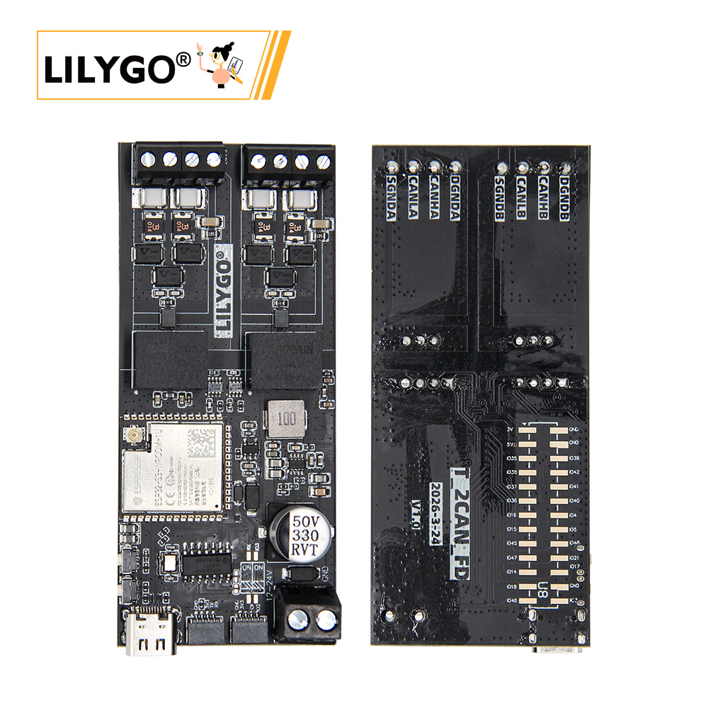
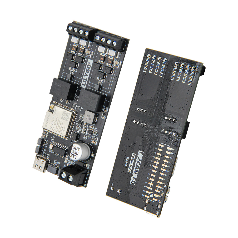
T-2Can-FD is an ESP32-S3-based development board with dual CAN FD bus interfaces. It provides two independent CAN buses: CAN bus 1 is driven by an external MCP2518FD controller (SPI, CAN-FD capable, compatible with CAN 2.0), and CAN bus 2 uses the ESP32-S3's built-in TWAI controller (CAN 2.0B). Ideal for industrial communication, vehicle diagnostics, robot control, and other CAN bus applications that require high reliability and high throughput.
Usage Notes:
- If firmware flashing fails, press and hold the
BOOT-0button and try again.- When using USB serial debugging, USB is configured as UART0 output by default. To use the external UART interface, change the CDC settings (see FAQ).
Quick Start
Example Support
| Example | PlatformIO / Arduino | Description |
|---|---|---|
| can | ✅ | CAN communication example (requires CAN FD adaptation) |
| original_test | ✅ | Factory test program |
PlatformIO
- Install Visual Studio Code and Python.
- Search for and install PlatformIO IDE in VS Code.
- Clone or download the project repository:
https://github.com/Xinyuan-LilyGO/T-2Can. - Open the project folder in VS Code.
- Open
platformio.ini, and uncomment the desired example under[platformio](default_envs = xxx) for the T-2Can-Fd configuration. - Click the lower-left ✓ to build.
- Connect the board and click → to upload.
Arduino IDE
- Install Arduino IDE.
- Install ESP32 board support: Tools → Board → Board Manager → search for
esp32and installEspressif Systems. - Select the board: ESP32S3 Dev Module.
- Copy all libraries from the project's
librariesdirectory into the Arduino libraries folder (Sketchbook location/libraries). - Open the example sketch (
.ino) from theexamplesdirectory. - Select the following settings in the Tools menu:
| Arduino IDE (ESP32-S3) | Value |
|---|---|
| Board | ESP32S3 Dev Module |
| Upload Speed | 921600 |
| USB Mode | Hardware CDC and JTAG |
| USB CDC On Boot | Enabled |
| USB Firmware MSC On Boot | Disabled |
| USB DFU On Boot | Disabled |
| CPU Frequency | 240MHz (WiFi) |
| Flash Mode | QIO 80MHz |
| Flash Size | 16MB (128Mb) |
| Core Debug Level | None |
| Partition Scheme | 16M Flash (3MB APP/9.9MB FATFS) |
| PSRAM | OPI PSRAM |
| Arduino Runs On | Core 1 |
| Events Run On | Core 1 |
- Select the correct port and click Upload.
Firmware Burning (using flash tool)
- Open the ESP32 flash tool in the project's
toolsdirectory. - Select the correct chip and flashing method, then click OK.
- Select the firmware file in the
firmware/directory, set the address, choose the port, and click burn. - If burning fails, press and hold the BOOT-0 button and try again.
Related Videos
No video tutorials yet, contributions are welcome.
Key Features
- MCU: ESP32-S3-WROOM-1U (16 MB Flash + 8 MB PSRAM)
- CAN bus 1: external MCP2518FD controller via SPI (CAN-FD, compatible with CAN 2.0)
- CAN bus 2: ESP32-S3 built-in TWAI controller (CAN 2.0B)
- Supports Wi-Fi + Bluetooth 5.0 LE
- USB powered with onboard 5V buck converter
- External UART expansion interface (CDC can be switched by configuration)
- Compact design suitable for automotive and industrial fieldbus applications
Product Parameters
| Feature | Specification |
|---|---|
| MCU | ESP32-S3-WROOM-1U |
| Flash | 16 MB |
| PSRAM | 8 MB |
| CAN Bus 1 | MCP2518FD (SPI, CAN-FD) |
| CAN Bus 2 | ESP32-S3 built-in TWAI (CAN 2.0B) |
| Interface | SPI |
| Wireless | Wi-Fi 802.11 b/g/n + Bluetooth 5.0 LE |
| Power | USB 5V |
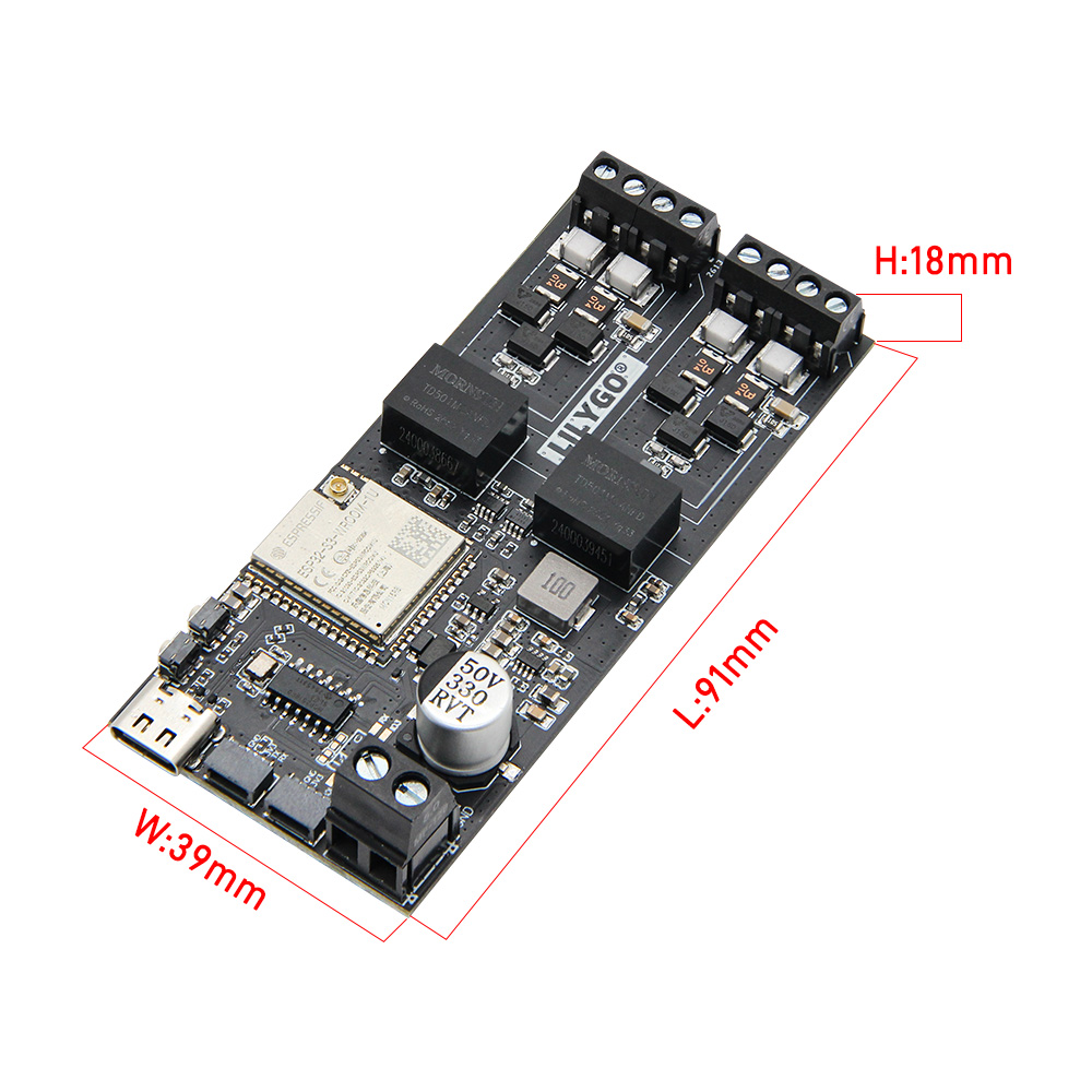
| Dimensions | TBD |
Pinout Diagram
Pin definitions refer to the configuration file:
pin_config.h
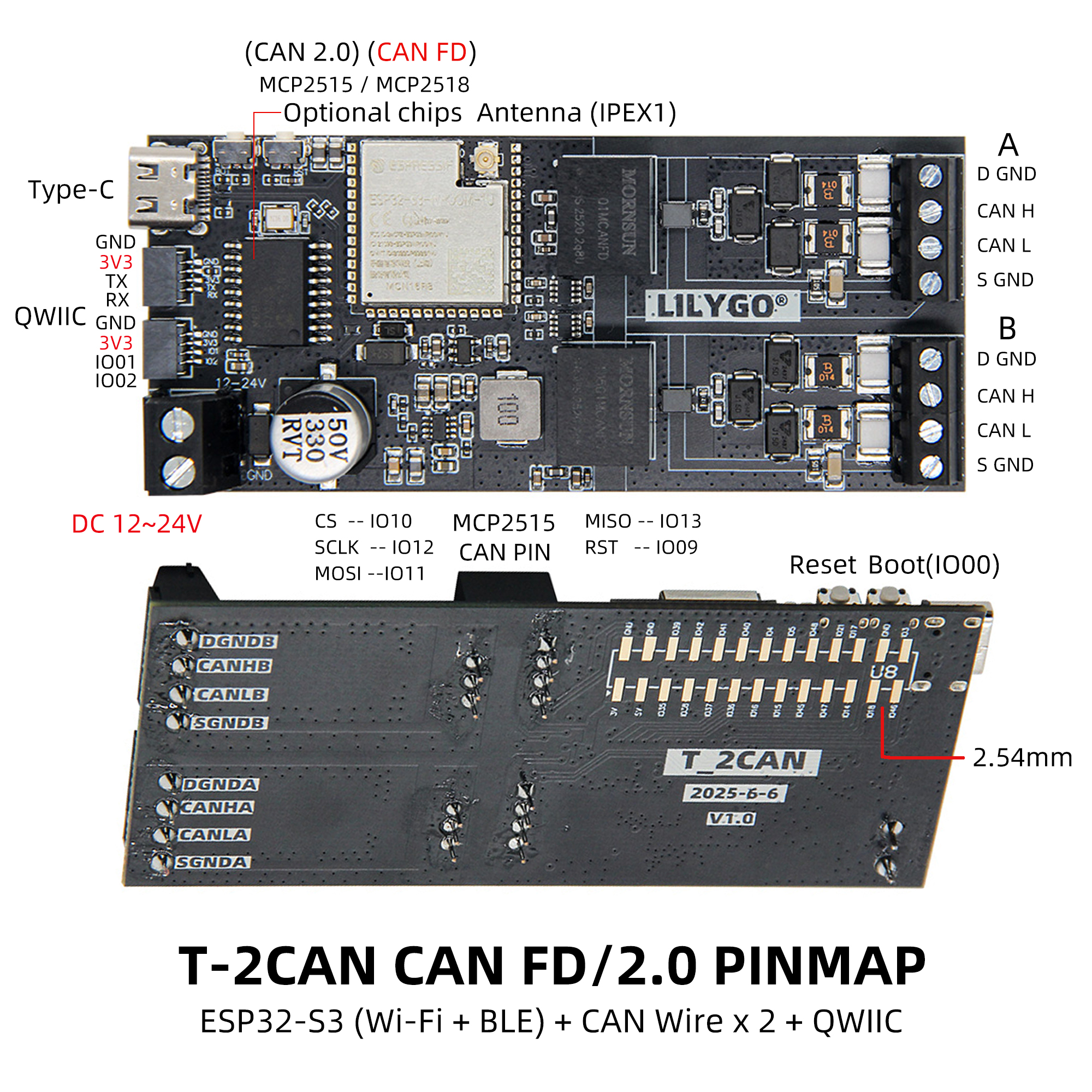
See the header file above for GPIO mapping, SPI chip select, interrupt pins, and other details.
Main Interface Description
| Interface | Description |
|---|---|
| CAN1 | MCP2518FD CAN-FD controller, SPI chip select CS1 |
| CAN2 | ESP32-S3 built-in TWAI controller |
| USB | Default UART0 debug output |
| UART Interface | External UART0 (requires CDC disabled) |
| BOOT-0 | Download mode button |
| RST | Reset button |
Dimension Diagram
Schematic
Datasheet
Software Development
- T-2Can GitHub Repository
- Longan_CANFD library (for MCP2518)
FAQ
Q: I still can't set up the development environment after reading the guide. What should I do?
A: Refer to LilyGo-Document for more detailed setup guidance.
Q: When Arduino IDE prompts me to update libraries, should I update them?
A: Choose not to update. Different library versions may be incompatible; it is recommended to use the project-provided library versions.
Q: Why is there no serial output on the board's UART interface?
A: The project uses USB as UART0 output by default. To use the external UART interface:
- PlatformIO users: modify
platformio.iniand setbuild_flags = -DARDUINO_USB_CDC_ON_BOOT=truetofalse. - Arduino users: set USB CDC On Boot to Disabled in the Tools menu.
Q: Why does flashing keep failing?
A: Press and hold the BOOT-0 button while retrying the download.
Q: Is T-2Can-Fd compatible with T-2Can firmware?
A: No. T-2Can-Fd uses MCP2518FD for CAN bus 1 and ESP32-S3 TWAI for CAN bus 2, requiring corresponding libraries and examples.
Version History
| Version | Release Date | Update Notes |
|---|---|---|
| T-2Can-Fd V1.0 | 2026-04-10 | Initial release, MCP2518FD + ESP32-S3 TWAI |