T-Beam 1W get it now
Overview
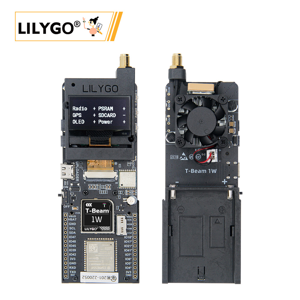
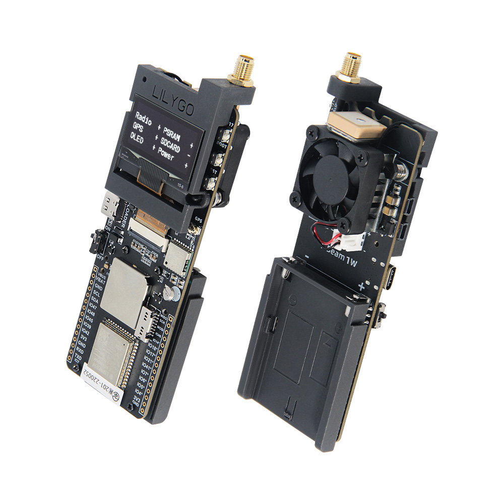
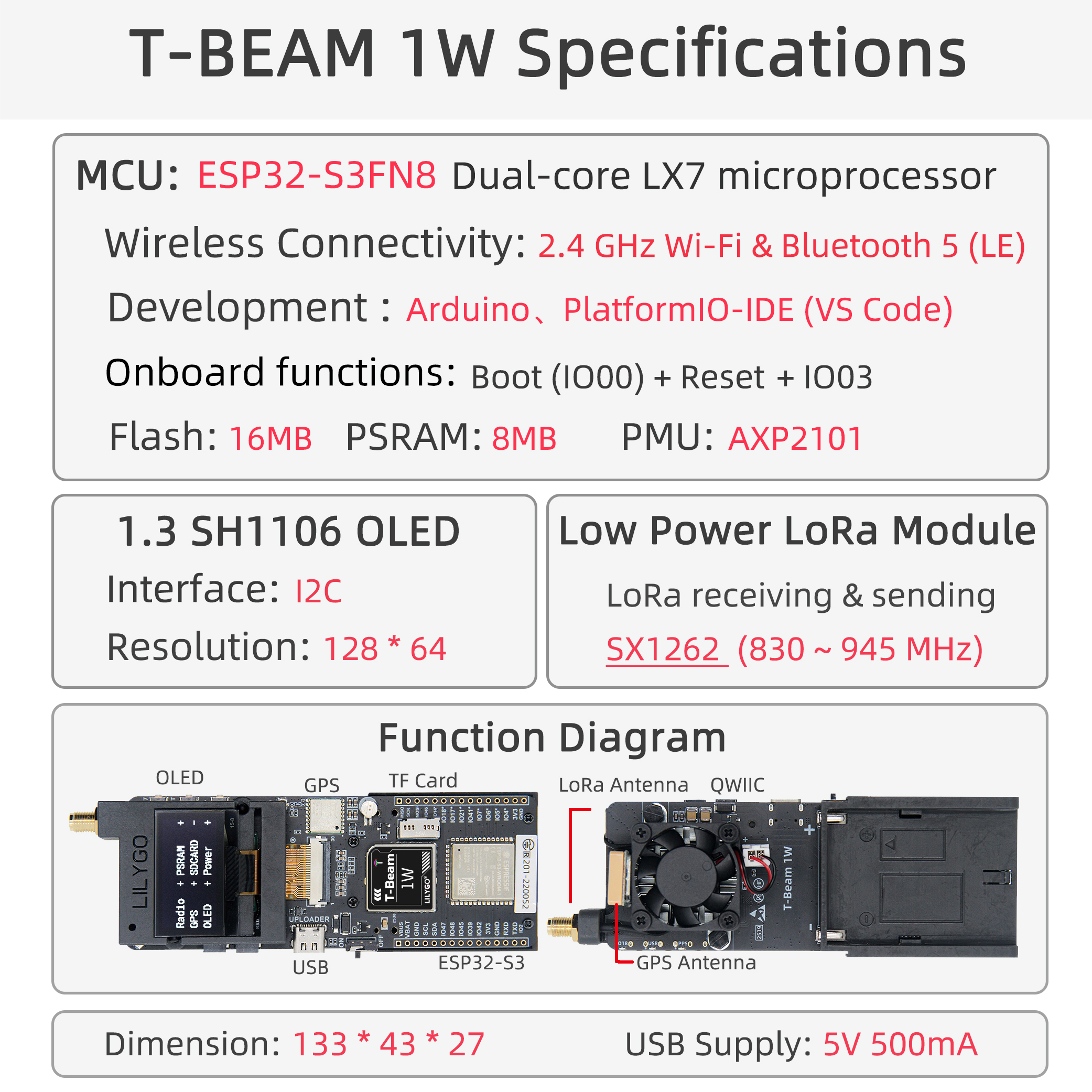
T-Beam-1W is a high-performance IoT development board integrating ESP32-S3 dual-core processor, LoRa SX1262 module (max 32 dBm output power), GPS L76K positioning module, SH1106 OLED screen, and AXP2101 power management chip. Onboard TF card slot, QWIIC interface, and external antenna interface; supports Wi-Fi, Bluetooth 5.0, and LoRa communication. Suitable for long-distance communication, positioning tracking, environmental monitoring, and other application scenarios.
Usage Notes:
- This board does not charge external 7.4V batteries — powered by battery only.
- Always connect the antenna before transmission to avoid damaging the RF module.
- GPIOs marked ❌ in the pin table are already connected to internal modules and cannot be reused.
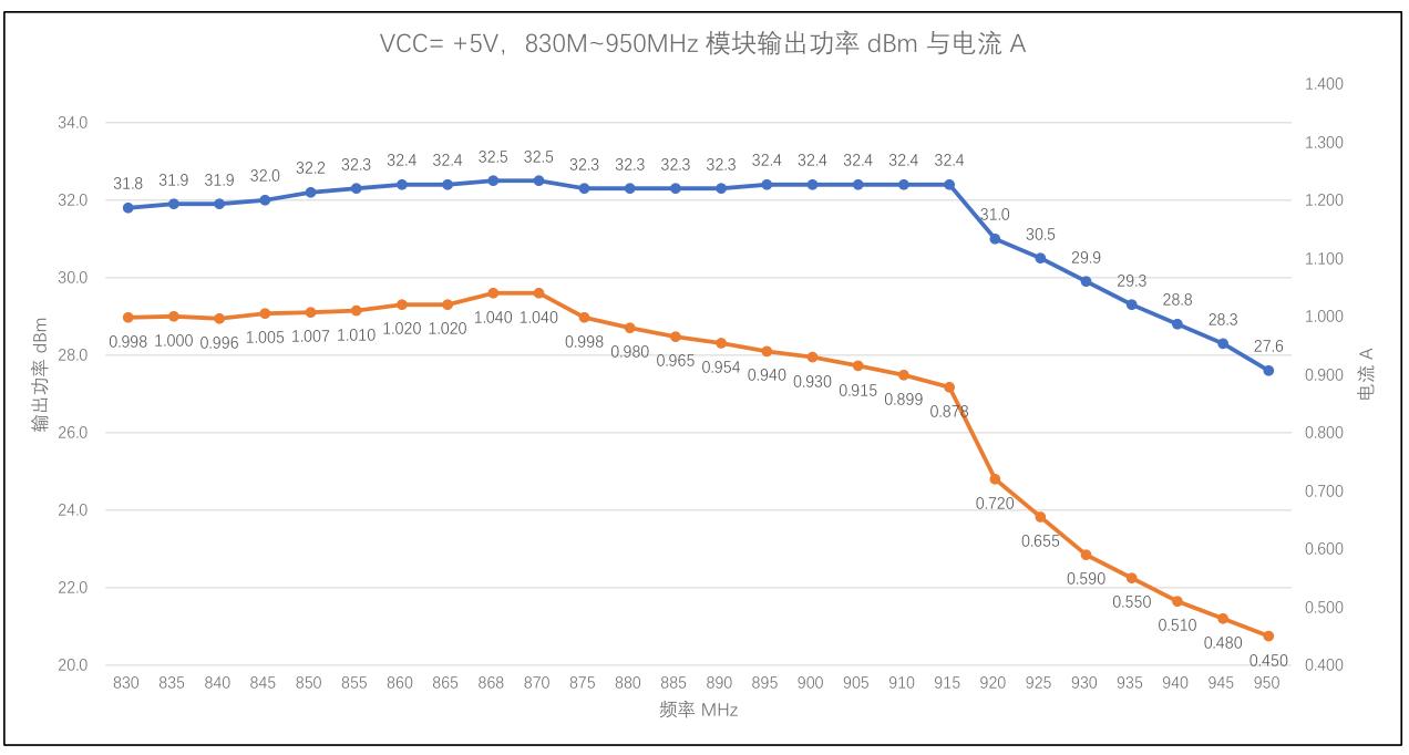
- The maximum output power of the RF module on this board is 32 dBm.
Quick Start
Example Support
| Example | PlatformIO/Arduino | ESP-IDF | Description |
|---|---|---|---|
| LilyGo-LoRa-Series | ✓ | LoRa, GPS, OLED examples |
PlatformIO
- Install Visual Studio Code and Python
- Search for and install the PlatformIO IDE extension in VS Code
- After restarting VS Code, click File → Open Folder → select the
LilyGo-LoRa-Seriesdirectory - Wait for third-party dependency libraries to install
- Open
platformio.ini, underdefault_envsuncomment the board name you want to use - Uncomment one
src_dir = xxxxline (only one active at a time) - Click ✓ at the bottom left to compile
- Connect the board via USB-C, click → to upload
- Click the plug symbol to open the serial monitor
Arduino
- Install Arduino IDE
- Install Arduino ESP32
- Copy all folders in the
libdirectory to your Arduino libraries folder:- Windows:
C:\Users\{username}\Documents\Arduino - macOS:
/Users/{username}/Documents/Arduino - Linux:
/home/{username}/Arduino
- Windows:
- Open the example sketch (
.inofile) from theexamplesdirectory - In Tools → Board, configure:
| Arduino IDE Setting | Value |
|---|---|
| Board | ESP32S3 Dev Module |
| Port | Your port |
| USB CDC On Boot | Enable |
| CPU Frequency | 240MHZ(WiFi) |
| Core Debug Level | None |
| USB DFU On Boot | Disable |
| Erase All Flash Before Sketch Upload | Disable |
| Flash Mode | QIO 80Mhz |
| Flash Size | 16MB(128Mb) |
| Arduino Runs On | Core1 |
| USB Firmware MSC On Boot | Disable |
| Partition Scheme | 16M Flash (3MB APP/9.9MB FATFS) |
| PSRAM | OPI PSRAM |
| Upload Speed | 921600 |
| Programmer | Esptool |
- In
utilities.h, uncomment your board model (e.g.,T_BEAM_1W) before compiling - Click Upload
Video
Key Features
- ESP32-S3FN8 dual-core LX7 @ 240 MHz, Wi-Fi 2.4 GHz + Bluetooth 5.0 LE
- SX1262 LoRa module, 830–945 MHz, max 32 dBm output power
- L76K GPS module with multi-constellation positioning support
- 1.3-inch SH1106 OLED display (128 × 64)
- AXP2101 power management, USB-C power, 7.4 V battery input
- 16 MB Flash + 8 MB OPI PSRAM + TF card expansion
- QWIIC / I²C expansion interface
- Onboard fan control (GPIO41)
Product Parameters
| Feature | Specification |
|---|---|
| MCU | ESP32-S3FN8 @ Dual-core LX7, 240 MHz |
| Flash | 16 MB |
| PSRAM | 8 MB (OPI PSRAM) |
| Wi-Fi | 2.4 GHz 802.11 b/g/n |
| Bluetooth | Bluetooth 5.0 LE |
| LoRa Module | SX1262, 830–945 MHz, max 32 dBm |
| GPS Module | L76K, multi-constellation |
| Display | 1.3-inch SH1106 OLED, 128 × 64 |
| Power Management | AXP2101 |
| USB Input Voltage | 3.9 V – 6 V |
| Battery Voltage | 7.4 V (no charging support) |
| Storage Expansion | TF card slot |
| Dimensions | 133 × 43 × 27 mm |
Pin Diagram
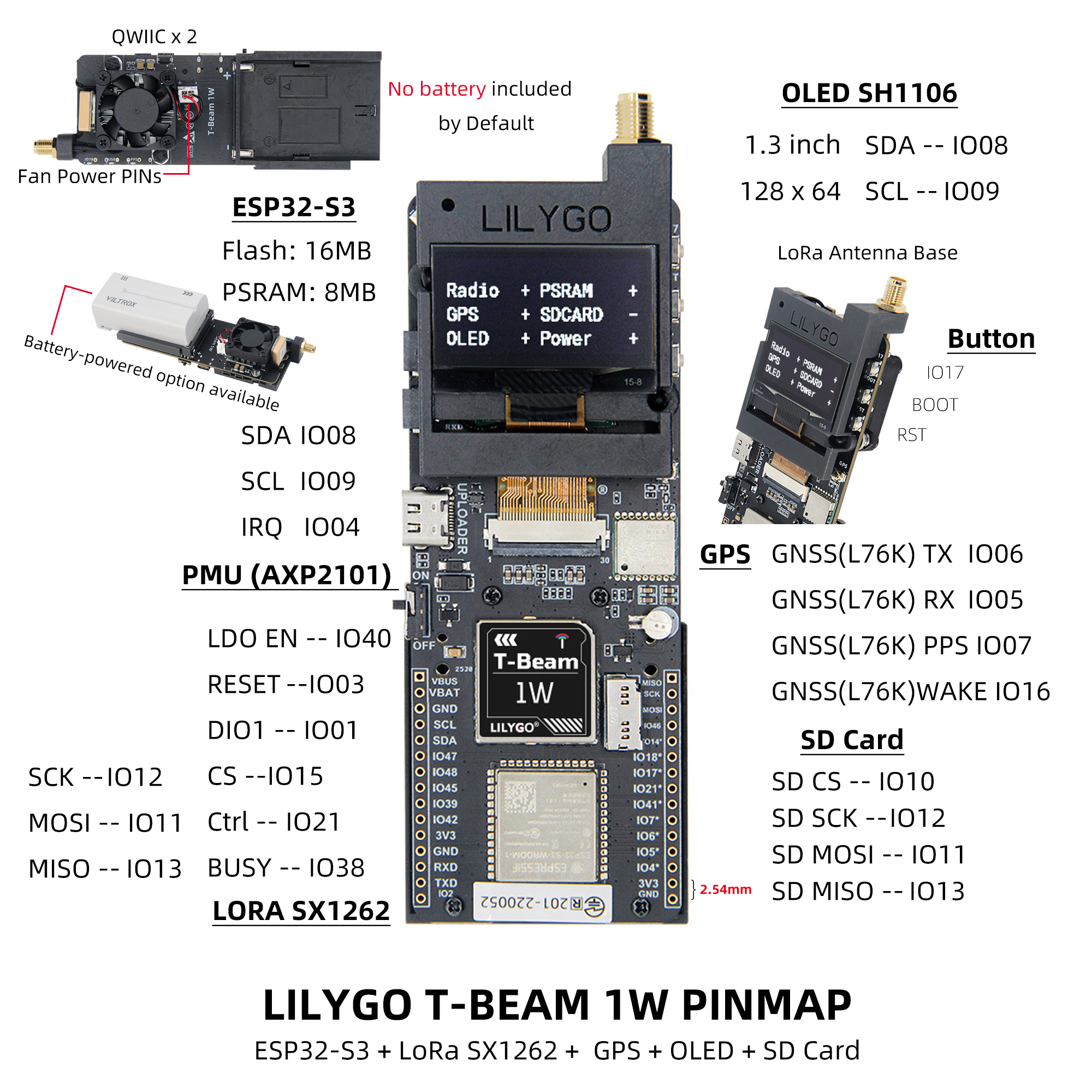
Pin Mapping
| Pin Name | GPIO | Available |
|---|---|---|
| Uart1 TX | 43 | ✅ |
| Uart1 RX | 44 | ✅ |
| I2C SDA | 8 | ❌ |
| I2C SCL | 9 | ❌ |
| SPI MOSI | 11 | ❌ |
| SPI MISO | 12 | ❌ |
| SPI SCK | 13 | ❌ |
| SD CS | 10 | ❌ |
| GPS TX | 6 | ❌ |
| GPS RX | 5 | ❌ |
| GPS PPS | 7 | ❌ |
| GPS Wake-up | 16 | ❌ |
| LoRa RESET | 3 | ❌ |
| LoRa DIO1 | 1 | ❌ |
| LoRa CS | 15 | ❌ |
| LoRa LDO EN | 40 | ❌ |
| LoRa Ctrl | 21 | ❌ |
| LoRa BUSY | 38 | ❌ |
| BOOT Button | 0 | ❌ |
| Custom Button | 17 | ❌ |
| Onboard LED | 18 | ❌ |
| NTC ADC | 14 | ❌ |
| Battery ADC | 4 | ❌ |
| Fan Control | 41 | ❌ |
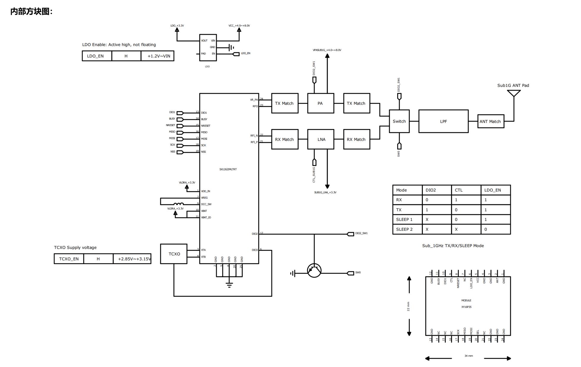
LDO EN is the module internal enable pin (high = Radio ON). LoRa Ctrl is the internal LNA control pin (high = RX mode, low = TX/sleep).
Buttons and LED
| Button | Function |
|---|---|
| IO17 | Custom Button |
| BOOT | Download Mode / Custom |
| RST | Reset |
| PWR | Long press 6 s to shut down |
| LED | Description |
|---|---|
| IO18 LED | Controlled by GPIO18 |
| PPS LED | Flashes with GPS pulse |
| USB LED | Lights up when USB is connected |
Dimension Diagram
Schematic
Datasheet
Software Development
FAQ
Q. USB device keeps flashing during upload? A. Check that the correct board model is selected, and ensure the macro definition in
utilities.his enabled (e.g.,#define T_BEAM_1W).Q. LoRa transmission distance is very short? A. Confirm antenna is connected, RF Switch is correctly switched, and output power is set reasonably.
Q. Board does not power on with battery? A. Check battery voltage (should be ~7.4 V) and ensure discharge capability ≥ 2A to handle high-power transmission.
Q. GPS positioning slow or no signal? A. Use in an outdoor open environment and check antenna connection.
Version History
| Version | Release Date | Update Description |
|---|---|---|
| T-Beam-1W V1.0 | 2024-06-15 | Initial Version |
| T-Beam-1W V1.1 | 2024-08-22 | Optimized power circuit, added fan control |
Related Tests
RF Parameters
| Band | Module | Frequency Range | Max Output Power | Modulation |
|---|---|---|---|---|
| 868 MHz | SX1262 (XY16P35) | 830–950 MHz | 32 dBm | LoRa / FSK / GMSK |
| 433 MHz | SX1262 (XY16P354) | 400–520 MHz | 32 dBm | LoRa / FSK / GMSK |
RF Precautions: Always connect antenna before transmission. Recommended PA stabilization time > 800 µs. Switch RF Switch to TX channel before transmission, otherwise PA may be damaged.
RF Block Diagram
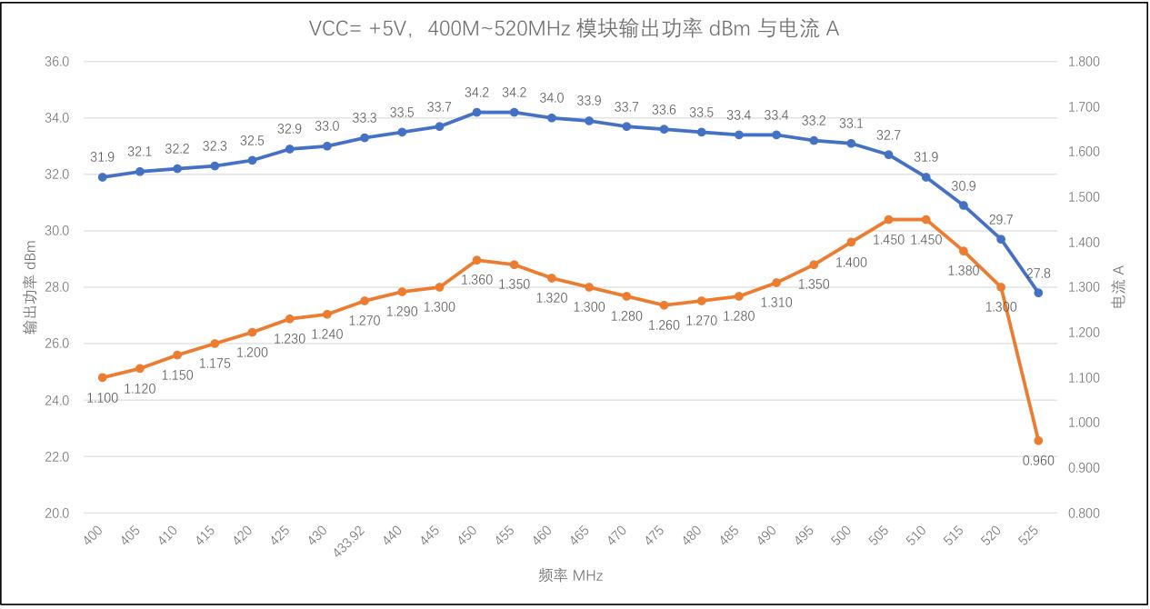
VCC = +5V, 400–520 MHz Output Power and Current
VCC = +5V, 830–950 MHz Output Power and Current