
T-PCIE get it now
Overview
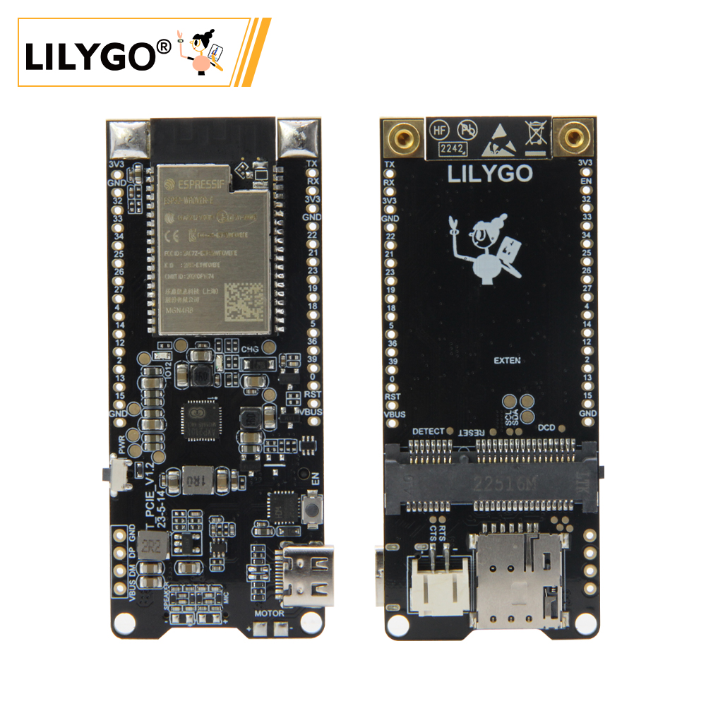
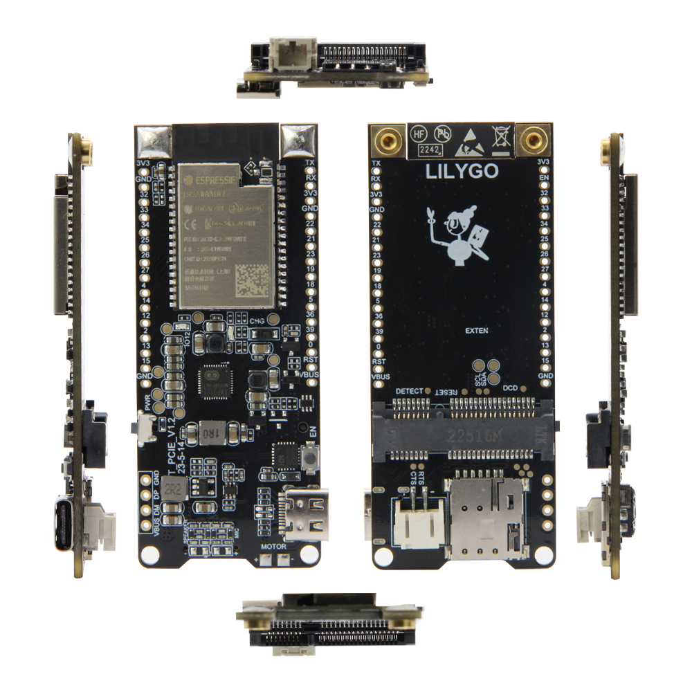
LILYGO T-PCIE is an ESP32-based cellular development board featuring a Mini PCIe (mPCIe) socket for interchangeable cellular modem modules. Powered by the ESP32-WROVER-E (dual-core Xtensa LX6, 240 MHz, 4 MB / 16 MB Flash, 8 MB PSRAM) with Wi-Fi and Bluetooth 4.2. Compatible modem modules include SIM7000G (NB-IoT/Cat-M), SIM7600X (LTE Cat-4), A7608X, SIM7670G, and SIM7080G. The AXP2101 PMU manages power for both the ESP32 and the modem. Suitable for cellular IoT gateways, remote monitoring nodes, and portable LTE/NB-IoT data devices.
Quick Start
Example Support
| Example | PlatformIO/Arduino | ESP-IDF | Description |
|---|---|---|---|
| LilyGo-Modem-Series | ✓ | Cellular AT commands, MQTT, HTTP examples |
PlatformIO
- Install the CH9102 USB bridge driver (Windows / Mac OS)
- Install Visual Studio Code and Python
- Search for and install the PlatformIO IDE extension in VS Code, then restart
- Open the
LilyGo-Modem-Seriesproject folder - Open
platformio.ini, uncomment thedefault_envs = T-PCIE-XXXXline matching your modem - Uncomment one
src_dir = examples/xxxline for the example you want to run - Click ✓ to compile, connect via USB-C, click → to upload
Arduino
- Install the CH9102 USB bridge driver (Windows / Mac OS)
- Install Arduino IDE and Arduino ESP32
- Copy all folders from the project
lib/directory into your Arduinolibraries/folder - Configure Tools → Board:
| Arduino IDE Setting | Value |
|---|---|
| Board | ESP32 Dev Module |
| CPU Frequency | 240 MHz (WiFi/BT) |
| Flash Frequency | 80 MHz |
| Flash Mode | QIO |
| Flash Size | 4MB (32Mb) |
| Partition Scheme | Huge APP (3MB No OTA/1MB SPIFFS) |
| PSRAM | Enable |
| Upload Speed | 921600 |
- Click Upload
Note: Do not update libraries when prompted in Arduino IDE — updated versions may break compatibility or overwrite default configurations (e.g. TinyGSM).
Development Platforms
Related Videos
Key Features
- ESP32-WROVER-E dual-core Xtensa LX6 @ 240 MHz, Wi-Fi 2.4 GHz + Bluetooth 4.2
- Mini PCIe (mPCIe) socket — swap modem modules without rework
- Compatible with SIM7000G, SIM7600X, A7608X, SIM7670G, SIM7080G
- AXP2101 PMU for ESP32 and modem power management
- Nano SIM card slot
- USB-C for programming and power
- 4 MB or 16 MB Flash, 8 MB PSRAM
- 18650 battery holder + solar charging
Specifications
| Parameter | Value |
|---|---|
| SOC | ESP32-WROVER-E, dual-core LX6 @ 240 MHz |
| Flash | 4 MB or 16 MB (Quad-SPI) |
| PSRAM | 8 MB (Quad-SPI) |
| Wi-Fi | 2.4 GHz 802.11 b/g/n |
| Bluetooth | 4.2 |
| Cellular | Via mPCIe module (SIM7000G / SIM7600X / A7608X / SIM7670G / SIM7080G) |
| PMU | AXP2101 |
| SIM | Nano SIM |
| USB | 1 × USB-C |
| Battery | 18650 holder + JST solar input |
Modem Module Compatibility
| Modem | Standard | Notes |
|---|---|---|
| SIM7000G | NB-IoT / LTE Cat-M / GPRS | GPS included |
| SIM7600X | LTE Cat-4 | Multiple regional variants |
| A7608X | LTE Cat-4 / Cat-1 | Multiple regional variants |
| SIM7670G | LTE Cat-1 | Multiple regional variants |
| SIM7080G | NB-IoT / Cat-M | GPS included |
DIP Switch
| Name | GPIO | ON | OFF |
|---|---|---|---|
| Pin 1 | 27 | Connect Modem TX to ESP | Disconnect |
| Pin 2 | 26 | Connect Modem RX to ESP | Disconnect |
| Pin 3 | NC | No connect | No connect |
| Pin 4 | PWRKEY | Modem power controlled by ESP | Auto power-on at startup |
ESP programming mode — Pin 1 & 2 ON, Pin 4 OFF: modem UART routed to ESP32, ESP controls modem power.
USB Modem mode — Pin 1 & 2 OFF, Pin 4 ON: modem connected directly to USB for firmware update or dial-up internet.
Pin Map
| Name | GPIO | Free |
|---|---|---|
| Modem DC Booster Enable | 25 | ❌ |
| Modem TX | 27 | ❌ |
| Modem RX | 26 | ❌ |
| Modem PWRKEY | 4 | ❌ |
| Modem DTR | 32 | ❌ |
| Modem RING | 33 | ❌ |
| Board LED | 12 | ❌ |
| PMIC IRQ | 35 | ❌ |
| PMIC SDA | 21 | ✅ |
| PMIC SCL | 22 | ✅ |
- GPIO33 and above on ESP32 are input-only — cannot be used as output.
- I2C pins are shared with the AXP2101 PMU and cannot be changed.
- Do not connect external wires to GPIO4 (PWRKEY), GPIO25, GPIO32, or GPIO33 header positions.
Electrical Parameters
| Parameter | Value |
|---|---|
| USB-C Input Voltage | 5 V |
| USB-C Charge Max Current | 1000 mA |
| Battery Voltage | 3.7 V |
The charging current can be configured via the AXP2101 PMU, up to 1 A.
Button Description
| Button | Function |
|---|---|
| EN (near USB-C) | Reset the device |
| PWR | Hold 1 s to power on; hold 6 s to power off |
Antenna
| Connector | Function |
|---|---|
| SIM / MAIN | LTE main antenna |
| GPS / GNSS | Active GPS antenna |
LED Description
| LED | Color | Location |
|---|---|---|
| Modem Status | Red | On the modem module |
| Modem Network | Red | On the modem module |
| Charge | Blue | Near board LED |
Modem Status and Network LEDs cannot be turned off in software.
Pin Diagram
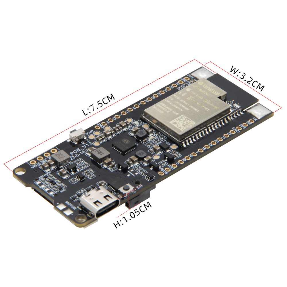
Dimension Diagram
Schematic
Datasheet
Software Development
Modem Module Pages
Dependent Libraries
FAQ
Q. Cannot upload sketch. A. Short GND and IO0, press RST, release RST, disconnect IO0 from GND, then upload. Alternatively hold BOOT and press RST.
Q. SIM card not detected. A. Insert the SIM card before powering on. Hot-inserting may cause detection failure.
Q. Which cellular modules are compatible? A. Tested with SIM7000G, SIM7600X, A7608X, SIM7670G, and SIM7080G in standard mPCIe form factor.
Q. Does the mPCIe slot carry PCIe signals? A. No — the mPCIe connector uses UART signals routed to the ESP32. This is the standard approach for cellular modem integration.
Q. Cannot put the modem into sleep mode. A. The T-PCIE series requires removing the VBUS inductor/resistor on the board to enable modem sleep mode.
Q. The board resets when switching between USB and battery. A. Expected behavior — no seamless power switching. Cannot be changed in software.
Changelog
| Version | Date | Notes |
|---|---|---|
| V1.2 | — | Current version |