
T-Dongle-S3-Plus get it now
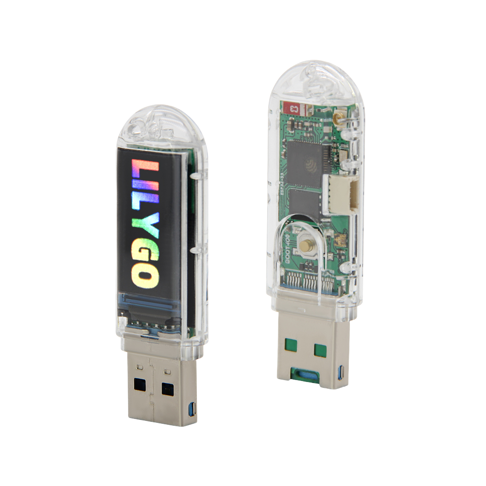
Overview
T-Dongle-S3-Plus is the enhanced version in the T-Dongle-S3 series. It uses an ESP32-S3 MCU with 16MB Quad-SPI Flash, 8MB OPI PSRAM, and 512KB SRAM. Compared with the standard T-Dongle-S3, the Plus version adds a PDM microphone, IR transmitter, optional I2C security chip, while keeping the 0.96-inch ST7735 SPI color display, APA102 RGB LED, TF card slot, QWIIC connector, and USB Type-A dongle form factor.
Quick Start
| Example | PlatformIO/Arduino | ESP-IDF | Description |
|---|---|---|---|
| T-Dongle-S3 | ✓ | Plus, display, TF card, LED, PDM, IR, QWIIC examples |
PlatformIO
- Install Visual Studio Code and PlatformIO IDE
- Clone and open the official repository:
git clone https://github.com/Xinyuan-LilyGO/T-Dongle-S3.git- Select the Plus environment and example in
platformio.ini - Click Build, plug in the device, then click Upload
Arduino
| Arduino IDE Setting | Value |
|---|---|
| Board | ESP32S3 Dev Module |
| USB CDC On Boot | Enable |
| CPU Frequency | 240MHz (WiFi) |
| Flash Mode | QIO 80MHz |
| Flash Size | 16MB (128Mb) |
| Partition Scheme | 16M Flash (3MB APP/9.9MB FATFS) |
| PSRAM | OPI PSRAM |
| Upload Speed | 921600 |
| USB Mode | Hardware CDC and JTAG |
Note: T-Dongle-S3-Plus has 8MB OPI PSRAM. Set PSRAM to OPI PSRAM in Arduino IDE.
Key Features
- ESP32-S3 MCU, Wi-Fi 802.11 b/g/n + Bluetooth 5 LE
- 16MB Quad-SPI Flash, 8MB OPI PSRAM, 512KB SRAM
- USB Type-A dongle form factor
- 0.96-inch ST7735 SPI color display, 160 × 80 resolution
- APA102 RGB LED
- TF card slot using SDMMC pins
- PDM microphone
- IR transmitter
- Optional I2C security chip
- QWIIC connector configured for serial port function by default
Specifications
| Parameter | Value |
|---|---|
| MCU | ESP32-S3 |
| Flash | 16MB (Quad-SPI) |
| PSRAM | 8MB (OPI PSRAM) |
| SRAM | 512KB |
| Wireless | Wi-Fi 802.11 b/g/n, Bluetooth 5 LE |
| Display | 0.96-inch ST7735 (SPI), 160 × 80 |
| RGB LED | APA102 × 1 |
| Storage | TF card slot |
| Microphone | PDM microphone |
| Infrared | IR transmitter |
| Security Chip | Optional I2C security chip |
| USB Input Voltage | 4.8V ~ 5.5V |
| USB Max Current | 800mA |
| USB | USB Type-A plug |
| QWIIC | Serial port function by default; add external pull-up resistors for I2C |
Pin Diagram
| Name | GPIO |
|---|---|
| RGB DIN | GPIO40 |
| RGB CLK | GPIO39 |
| SDMMC D0 | GPIO14 |
| SDMMC D1 | GPIO17 |
| SDMMC D2 | GPIO21 |
| SDMMC D3 | GPIO18 |
| SDMMC CLK | GPIO12 |
| SDMMC CMD | GPIO16 |
| Button | GPIO0 |
| QWIIC TX | GPIO43 |
| QWIIC RX | GPIO44 |
| PDM CLK | GPIO9 |
| PDM DATA | GPIO8 |
| IR | GPIO7 |
| I2C SDA (Encrypted Version Only) | GPIO11 |
| I2C SCL (Encrypted Version Only) | GPIO10 |
QWIIC Connector
The QWIIC connector is configured for serial port function by default. To use it for I2C, add pull-up resistors to the external sensor.
Encryption Chip Note
The encrypted version may include an ATECC508A. To prevent the chip from being locked, the factory only performs I2C probing to confirm that the encryption chip responds normally. It does not configure or read/write the ATECC508A. Once configured, the chip is locked by its inherent configuration, so make sure you understand the process before changing it.