T-Beam-BPF get it now
Overview
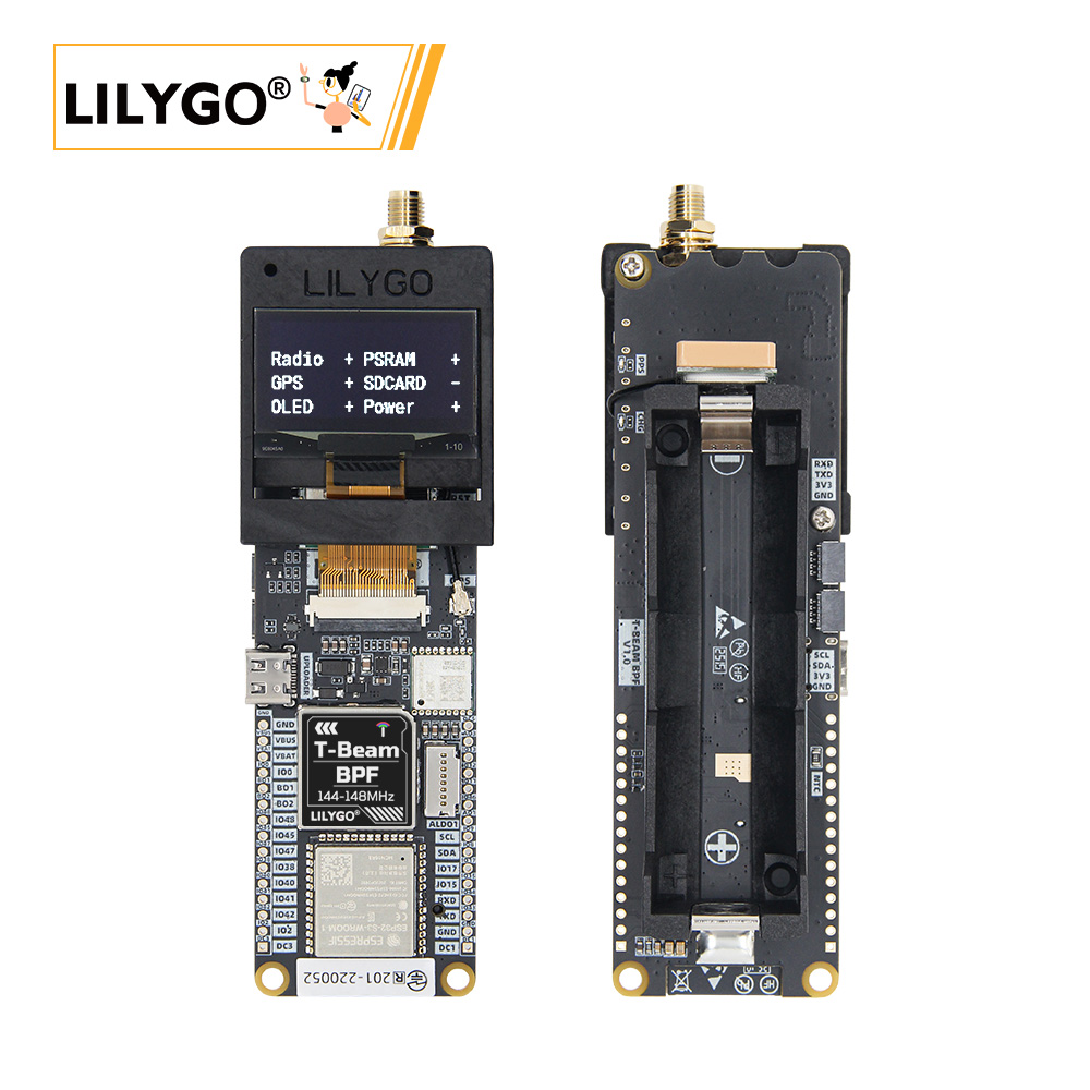
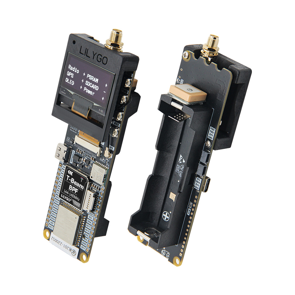
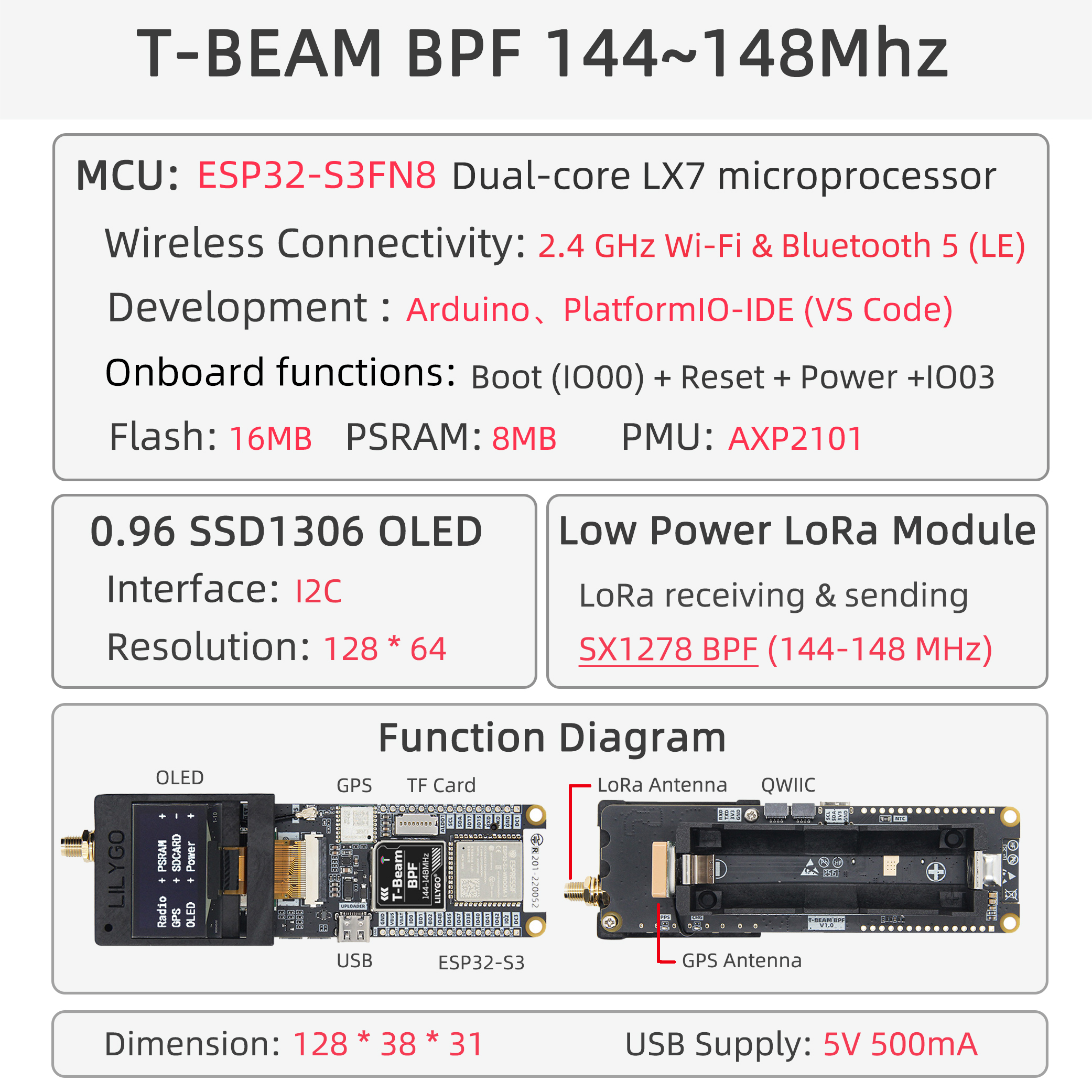
LILYGO T-Beam-BPF is a variant of the T-Beam series featuring an integrated Band-Pass Filter (BPF) for improved LoRa signal reception in the 144–148 MHz VHF band. Based on the ESP32-S3 dual-core LX7 with Wi-Fi and Bluetooth 5.0, it pairs with the SX1278 LoRa module to deliver enhanced selectivity and noise rejection — ideal for amateur radio, APRS, and interference-prone environments. Includes a 0.96-inch SH1106 OLED, GPS module (L76K), AXP2101 PMU, and 18650 battery support.
Notes on Use
- The device will not power on when a battery is inserted for the first time, because the onboard BMS is in shipping mode. Connect USB-C to activate the device. If the battery is removed and re-inserted, repeat this step.
- Always connect the antenna before transmitting, otherwise the RF module may be damaged.
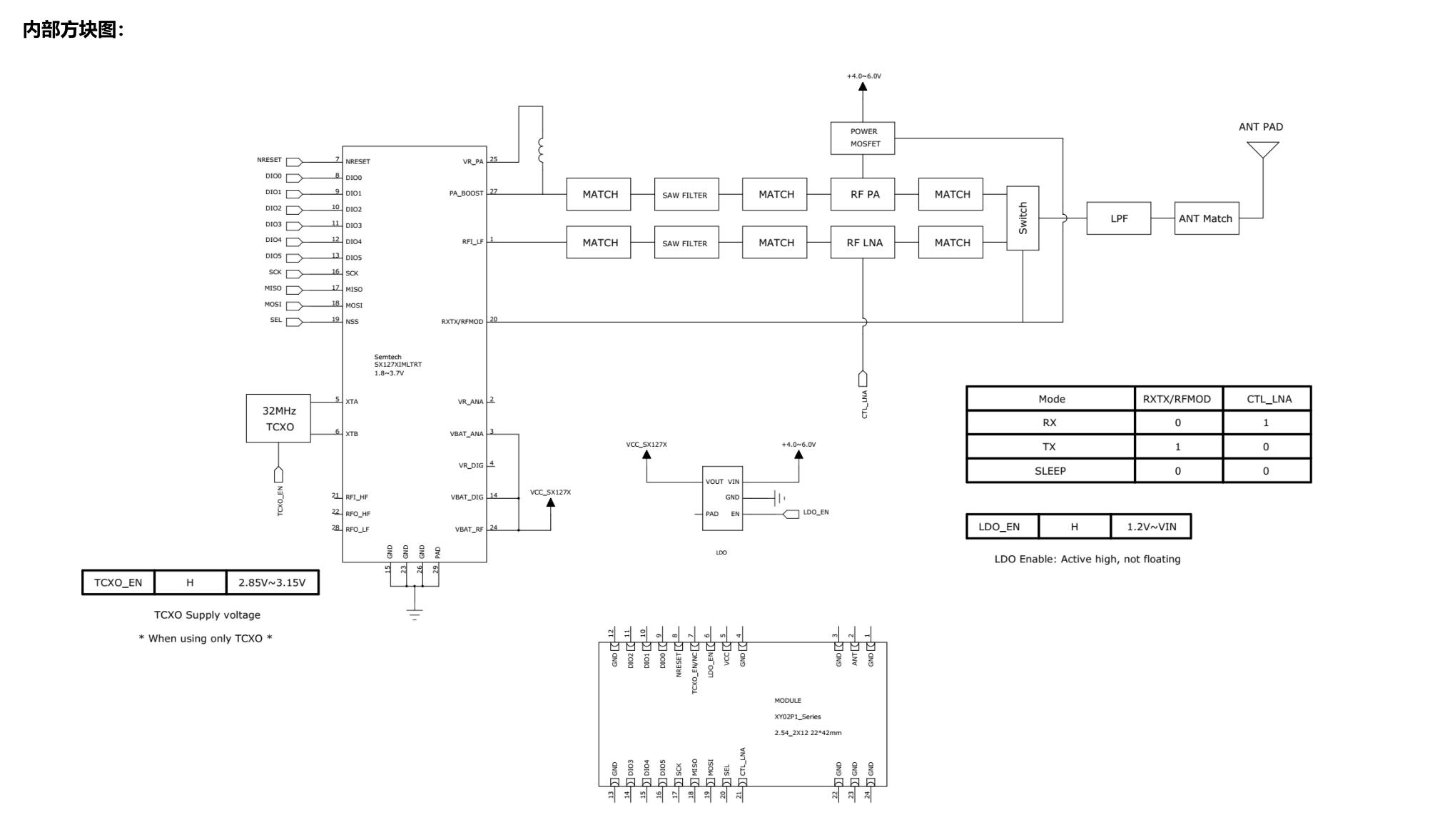
Block Diagram
Quick Start
Example Support
| Example | PlatformIO/Arduino | ESP-IDF | Description |
|---|---|---|---|
| LilyGo-LoRa-Series | ✓ | LoRa, GPS, OLED, PMU examples |
PlatformIO
- Install Visual Studio Code and Python
- Search for and install the PlatformIO IDE extension in VS Code, then restart VS Code
- Open the
LilyGo-LoRa-Seriesproject folder via File → Open Folder - Wait for third-party library installation to complete
- Open
platformio.ini, uncomment the T-Beam-BPF environment indefault_envs, and uncomment the matchingsrc_dirline - Click ✓ to compile, connect via USB-C, click → to upload
- Click the plug icon to monitor serial output
Arduino
- Install Arduino IDE
- Install Arduino ESP32
- Copy all folders in the
libdirectory to your ArduinoSketchbook location:- Windows:
C:\Users\{username}\Documents\Arduino - macOS:
/Users/{username}/Documents/Arduino - Linux:
/home/{username}/Arduino
- Windows:
- Open the desired example from
LilyGo-LoRa-Series/examples/ - In Tools → Board, configure:
| Arduino IDE Setting | Value |
|---|---|
| Board | ESP32S3 Dev Module |
| USB CDC On Boot | Enable |
| CPU Frequency | 240 MHz (WiFi) |
| Flash Mode | QIO 80 MHz |
| Flash Size | 16MB (128Mb) |
| Partition Scheme | 16M Flash (3MB APP/9.9MB FATFS) |
| PSRAM | OPI PSRAM |
| Upload Mode | UART0/Hardware CDC |
| Upload Speed | 921600 |
| USB Mode | CDC and JTAG |
| Programmer | Esptool |
- In
utilities.h, uncomment#define T_BEAM_S3_BPF - Click Upload
Development Platforms
Related Videos
Key Features
- ESP32-S3 dual-core LX7 @ 240 MHz, Wi-Fi + Bluetooth 5.0
- SX1278 TCXO LoRa with integrated Band-Pass Filter (144–148 MHz VHF)
- Enhanced signal selectivity and noise immunity
- 0.96-inch SH1106 OLED (128 × 64, I2C)
- L76K GPS module for location tracking
- AXP2101 power management unit
- 18650 battery holder with charging support
- USB-C for programming and power
Specifications
| Parameter | Value |
|---|---|
| SOC | ESP32-S3, Dual-core LX7 @ 240 MHz |
| Flash | 16 MB |
| PSRAM | 8 MB (OPI) |
| Wireless | Wi-Fi 2.4 GHz 802.11 b/g/n, Bluetooth 5.0 |
| LoRa | SX1278 TCXO with BPF, 144–148 MHz VHF |
| Display | 0.96-inch SH1106 OLED, 128 × 64, I2C |
| GPS | L76K |
| PMU | AXP2101 |
| Battery | 18650 Li-Ion holder |
| USB | 1 × USB-C |
Pin Diagram
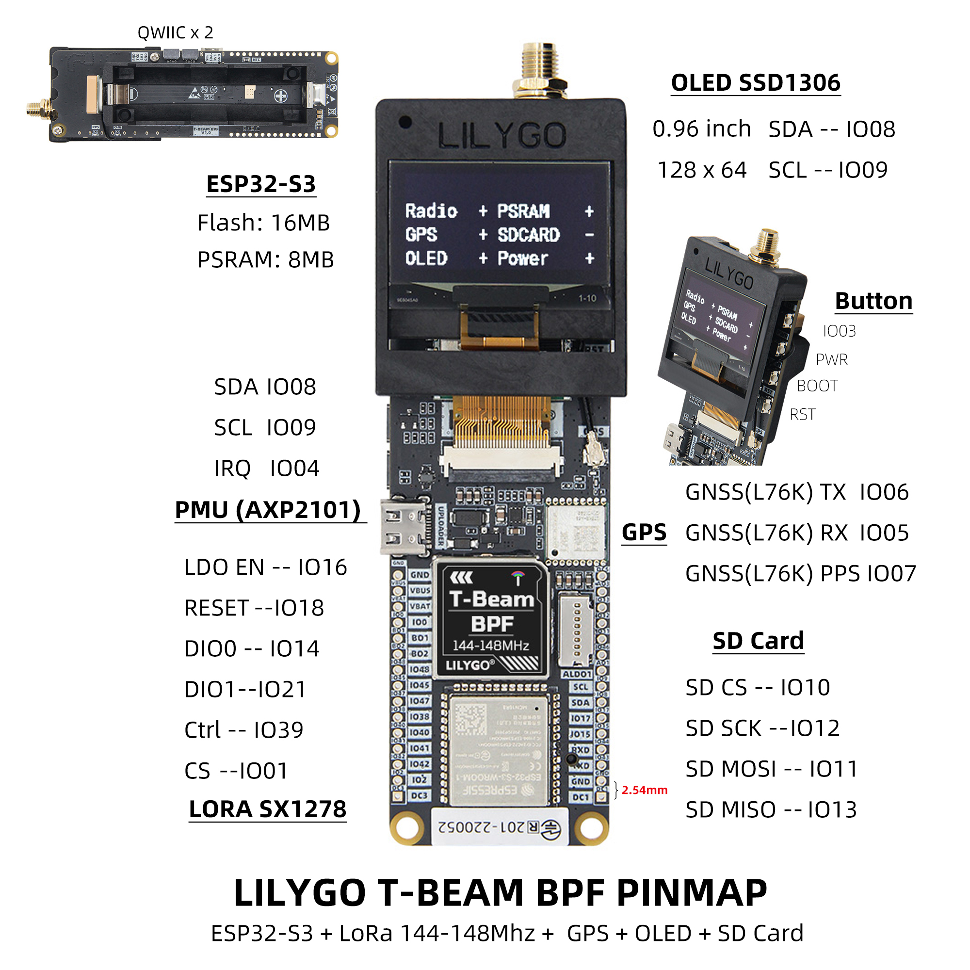
Pins Map
| Name | GPIO | Free |
|---|---|---|
| UART1 TX | 43 (External QWIIC Socket) | ✅ |
| UART1 RX | 44 (External QWIIC Socket) | ✅ |
| SDA | 8 (External QWIIC Socket) | ❌ |
| SCL | 9 (External QWIIC Socket) | ❌ |
| OLED (SH1106) SDA | Share with I2C bus | ❌ |
| OLED (SH1106) SCL | Share with I2C bus | ❌ |
| SPI MOSI | 11 | ❌ |
| SPI MISO | 13 | ❌ |
| SPI SCK | 12 | ❌ |
| SD CS | 10 | ❌ |
| SD MOSI | Share with SPI bus | ❌ |
| SD MISO | Share with SPI bus | ❌ |
| SD SCK | Share with SPI bus | ❌ |
| GNSS (L76K) TX | 6 | ❌ |
| GNSS (L76K) RX | 5 | ❌ |
| GNSS (L76K) PPS | 7 | ❌ |
| LoRa (SX1278) SCK | Share with SPI bus | ❌ |
| LoRa (SX1278) MISO | Share with SPI bus | ❌ |
| LoRa (SX1278) MOSI | Share with SPI bus | ❌ |
| LoRa (SX1278) RESET | 18 | ❌ |
| LoRa (SX1278) DIO0 | 14 | ❌ |
| LoRa (SX1278) DIO1 | 21 | ❌ |
| LoRa (SX1278) CS | 1 | ❌ |
| LoRa (SX1278) LDO EN | 16 | ❌ |
| LoRa (SX1278) Ctrl | 39 | ❌ |
| Button1 (BOOT) | 0 | ❌ |
| Button2 | 3 | ❌ |
| PMU (AXP2101) IRQ | 4 | ❌ |
| PMU (AXP2101) SDA | Share with I2C bus | ❌ |
| PMU (AXP2101) SCL | Share with I2C bus | ❌ |
Note: LDO EN is the Radio power control pin — High = Radio ON, Low = Radio OFF. LoRa Ctrl is the internal LNA power control — set High when receiving, Low when transmitting or sleeping.
I2C Device Addresses
| Device | 7-Bit Address | Shared Bus |
|---|---|---|
| OLED SH1106 | 0x3C | ✅ |
| PMU AXP2101 | 0x34 | ✅ |
Electrical Parameters
| Feature | Details |
|---|---|
| USB-C Input Voltage | 3.9 V – 6 V |
| Charge Current | 0 – 1024 mA (programmable) |
| Battery Voltage | 3.7 V |
Note: This board has an integrated BMS. On first battery connection, connect USB-C to activate. If the battery is disconnected and reconnected, repeat activation.
Power Management Channels
| Channel | Peripheral |
|---|---|
| DC1 | ESP32-S3 |
| DC2 | Unused |
| DC3 | External pin header |
| DC4 | Unused |
| DC5 | External pin header |
| LDO1 (VRTC) | Unused |
| ALDO1 | External pin header |
| ALDO2 | SD Card |
| ALDO3 | External pin header |
| ALDO4 | GNSS |
| BLDO1 | Unused |
| BLDO2 | External pin header |
| DLDO1 | Unused |
| CPUSLDO | Unused |
| VBACKUP | Unused |
Button Description
| Button | Function |
|---|---|
| IO3 | Customizable |
| PWR | PMU button — press to power on; hold 6 s to power off |
| BOOT | Boot mode / customizable |
| RST | Reset |
LED Description
- CHG LED: Always on while charging, off when fully charged. Can be controlled by firmware.
- PPS LED: Connected to GPS PPS pin. Flashes when PPS pulse arrives. Cannot be turned off.
RF Parameters
| Feature | Details |
|---|---|
| RF Module | SX1278 TCXO (XP02P181T) |
| Frequency Range | 144–148 MHz |
| Transfer Rate (LoRa) | 0.018 K–37.5 Kbps |
| Transfer Rate (FSK) | 1.2 K–300 Kbps |
| Modulation | FSK, GFSK, MSK, GMSK, LoRa, OOK |
RF Notes:
- Always connect the antenna before powering on to transmit.
- Switch the RF switch to TX/RX channel before transmitting/receiving (SX127X RXTX/RFMOD: High = TX, Low = RX).
- Maximum output power: +10 dBm, not exceeding +12 dBm.
- When dormant with TCXO_EN high, the TCXO oscillator consumes ~2.5 mA. Set TCXO_EN low for true sleep (SX127X config is lost and must be reinitialized on wake).
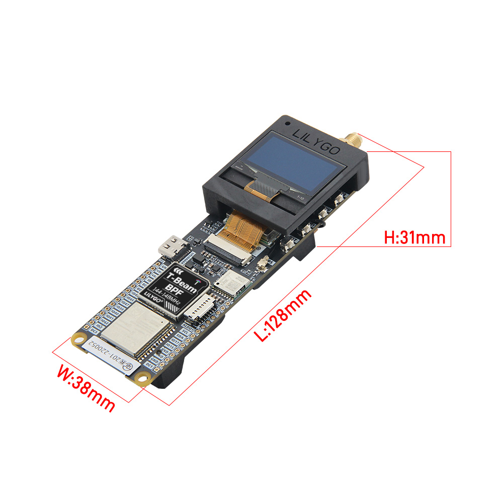
Dimensions
Schematic
Datasheet
Software Libraries
Dependent Libraries
FAQ
Q. What is the BPF (Band-Pass Filter)? A. The built-in band-pass filter limits the receivable frequency range to 144–148 MHz VHF, effectively reducing out-of-band interference and improving reception sensitivity in dense RF environments.
Q. Can it be used for APRS? A. Yes. The 144 MHz VHF band is the standard APRS frequency in most regions, and the BPF is specifically designed for this application.
Q. The device won't power on after inserting the battery. A. The onboard BMS ships in shipping mode. Connect USB-C to activate. If the battery is removed and reinserted, repeat this step.
Q. How do I enable PSRAM? A. In Arduino IDE, set PSRAM to OPI PSRAM. In ESP-IDF, enable SPIRAM support in menuconfig.
Changelog
| Version | Date | Notes |
|---|---|---|
| V1.0 | Initial release |