
T-Sim Shield get it now
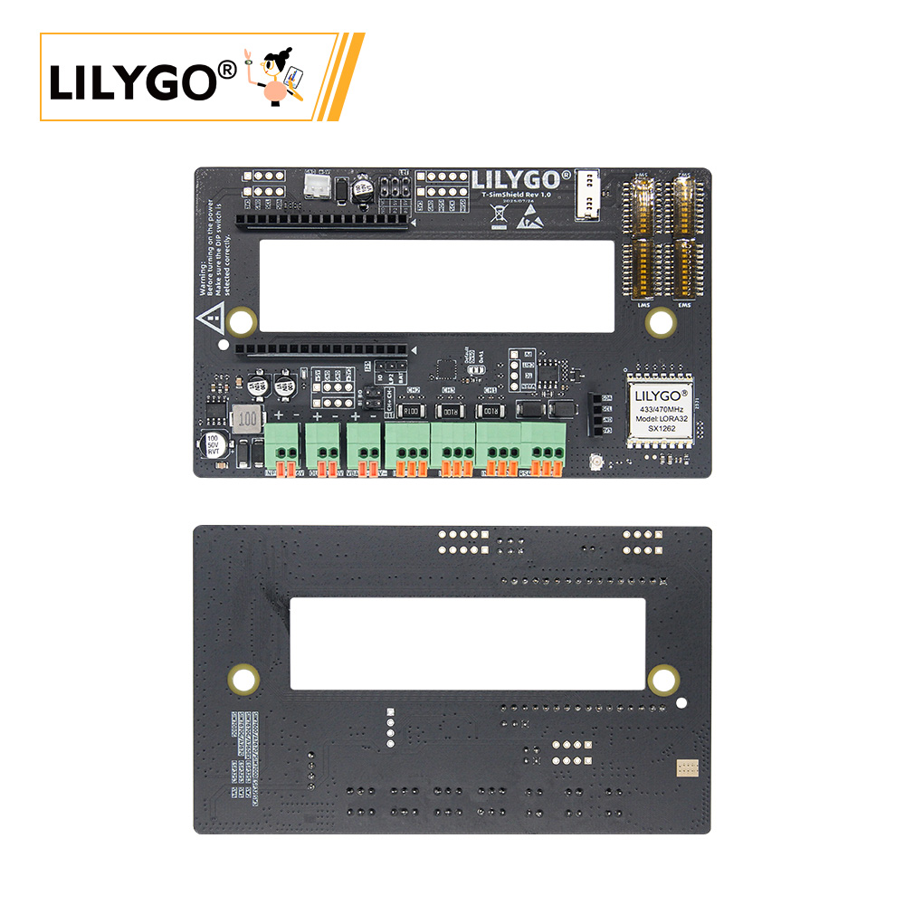
Overview
T-Sim Shield is a multifunction expansion board designed for the LilyGo T-Sim Series. Integrates INA3221 triple-channel current sensing, SX1262 LoRa long-range transceiver, RS485 (hardware auto direction control), 7–36 V DC wide-voltage input (with 5 V/2 A regulated output), I2C/SPI expansion interfaces, and SD card slot (remapped SPI). Compatible with all LilyGo T-Sim series mainboards via a stackable connector.
Important: Always verify jumper cap and DIP switch settings before powering on. Incorrect configuration may cause hardware damage.
Quick Start
Example Support
| Example | PlatformIO/Arduino | ESP-IDF | Description |
|---|---|---|---|
| SimShield_LoRaWAN | ✓ | LoRaWAN communication | |
| SimShield_LoRaReceive | ✓ | LoRa receive | |
| SimShield_LoRaTransmit | ✓ | LoRa transmit | |
| SimShieldCurrentSensor | ✓ | INA3221 current sensing | |
| SimShieldFactory | ✓ | Factory test | |
| SerialRS485 | ✓ | RS485 communication |
PlatformIO
- Install Visual Studio Code and Python
- Search for and install the PlatformIO IDE extension in VS Code
- Clone the LilyGo-Modem-Series repository
- Open
platformio.iniand uncomment the desired example - Click ✓ to compile, click → to upload
Arduino
Refer to the mainboard-specific Quick Start guide. Use the same libraries and Arduino settings as the matched T-Sim mainboard.
Development Platforms
Video
Key Features
- INA3221 triple-channel current sensing (battery charge/discharge monitoring)
- SX1262 LoRa transceiver (long-range wireless)
- 7–36 V DC wide-voltage input, 5 V/2 A output
- RS485 (hardware auto direction control, ≤115200 baud)
- SD card slot (SPI remapped from mainboard), I2C/SPI expansion
Product Parameters
| Feature | Specification |
|---|---|
| Current Sensing | INA3221, 3 channels |
| LoRa | SX1262 (SPI) |
| RS485 | Hardware auto direction (ADCDC) |
| DC Input | 7–36 V |
| Battery Input | 4.2 V max |
| 5 V Output | Max 2 A |
| Compatibility | All LilyGo T-Sim series mainboards |
Pin Diagram
Pin mappings vary by mainboard. Configure DIP switches and jumpers before use.
SIM7000G / A7670X / A7608X (ESP32):
| Signal | GPIO |
|---|---|
| SIMSHIELD_MOSI | 23 |
| SIMSHIELD_MISO | 19 |
| SIMSHIELD_SCK | 18 |
| SIMSHIELD_SD_CS | 32 |
| SIMSHIELD_RADIO_BUSY | 39 |
| SIMSHIELD_RADIO_CS | 5 |
| SIMSHIELD_RADIO_IRQ | 34 |
| SIMSHIELD_RADIO_RST | 15 |
| SIMSHIELD_RS_RX | 13 |
| SIMSHIELD_RS_TX | 14 |
| SIMSHIELD_SDA | 21 |
| SIMSHIELD_SCL | 22 |
SIM7670G (ESP32-S3):
| Signal | GPIO |
|---|---|
| SIMSHIELD_MOSI | 15 |
| SIMSHIELD_MISO | 7 |
| SIMSHIELD_SCK | 16 |
| SIMSHIELD_SD_CS | 46 |
| SIMSHIELD_RADIO_BUSY | 38 |
| SIMSHIELD_RADIO_CS | 39 |
| SIMSHIELD_RADIO_IRQ | 6 |
| SIMSHIELD_RADIO_RST | 40 |
| SIMSHIELD_RS_RX | 41 |
| SIMSHIELD_RS_TX | 42 |
| SIMSHIELD_SDA | 2 |
| SIMSHIELD_SCL | 1 |
For other mainboard pin mappings and jumper configurations, refer to the GitHub README.
Dimension Diagram
Schematic
Datasheet
Software Development
Dependent Libraries
FAQ
Q. Why is there no SD card slot output after inserting the card? A. After using the T-Sim Shield, insert the SD card into the expansion board, not the mainboard — the SPI bus is remapped.
Q. Can I use an external battery with the mainboard's 18650 socket? A. No. When using an external battery connected to the T-Sim Shield, do not install a battery in the mainboard's 18650 socket.
Q. What RS485 baud rate is recommended? A. ≤115200 baud is recommended for reliable communication.
Version History
| Version | Release Date | Update Description |
|---|---|---|
| T-SimShield Rev1.0 | 2024-08-10 | Initial release |
| T-SimShield Rev1.1 | 2024-11-05 | Optimized power circuit for stability |