
T-Display-CM0
Overview
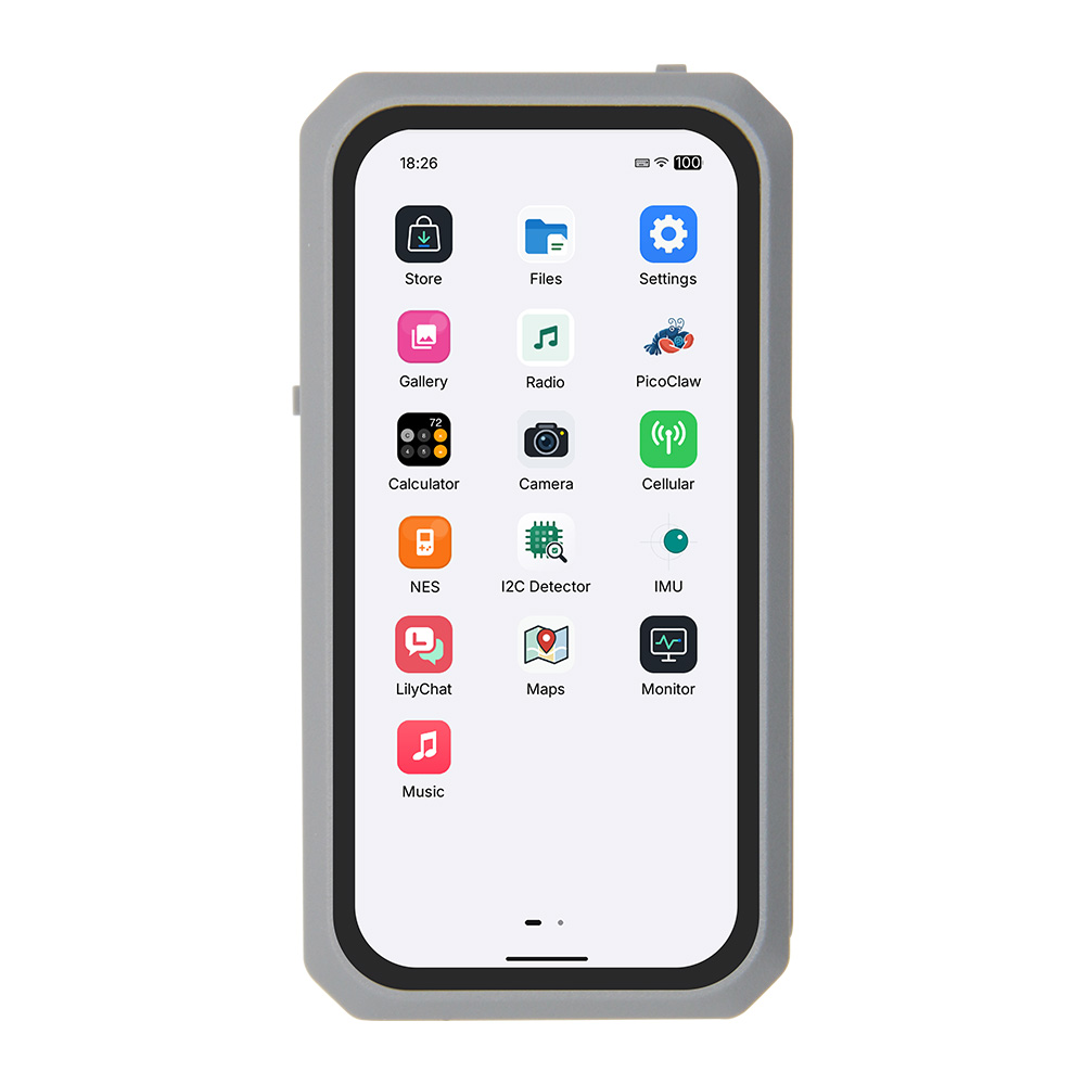
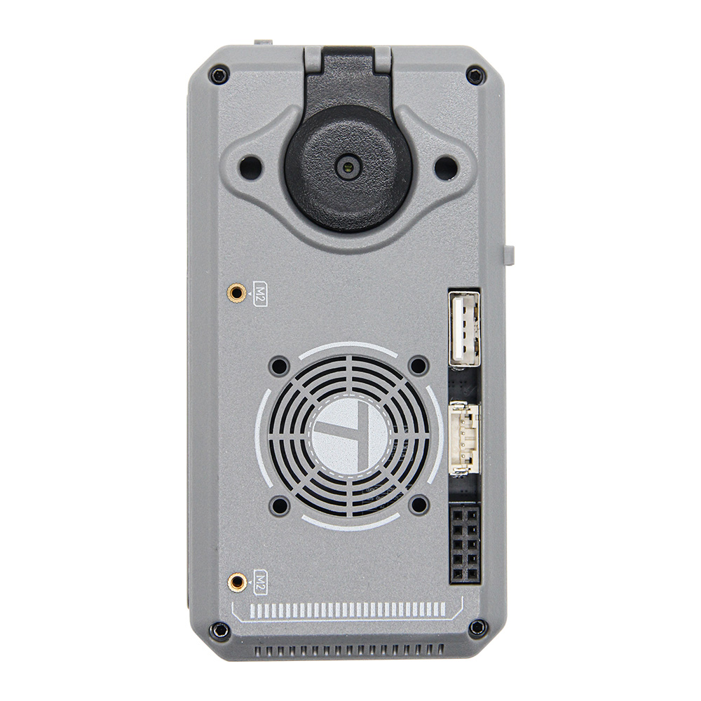
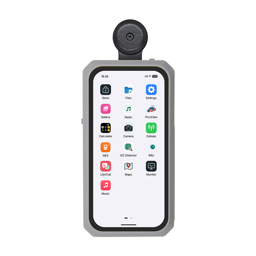
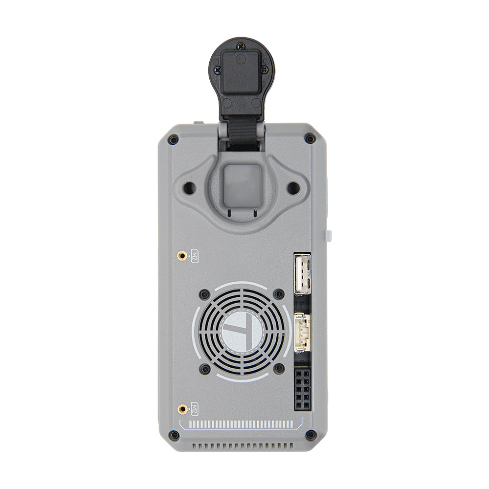
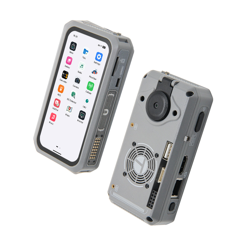
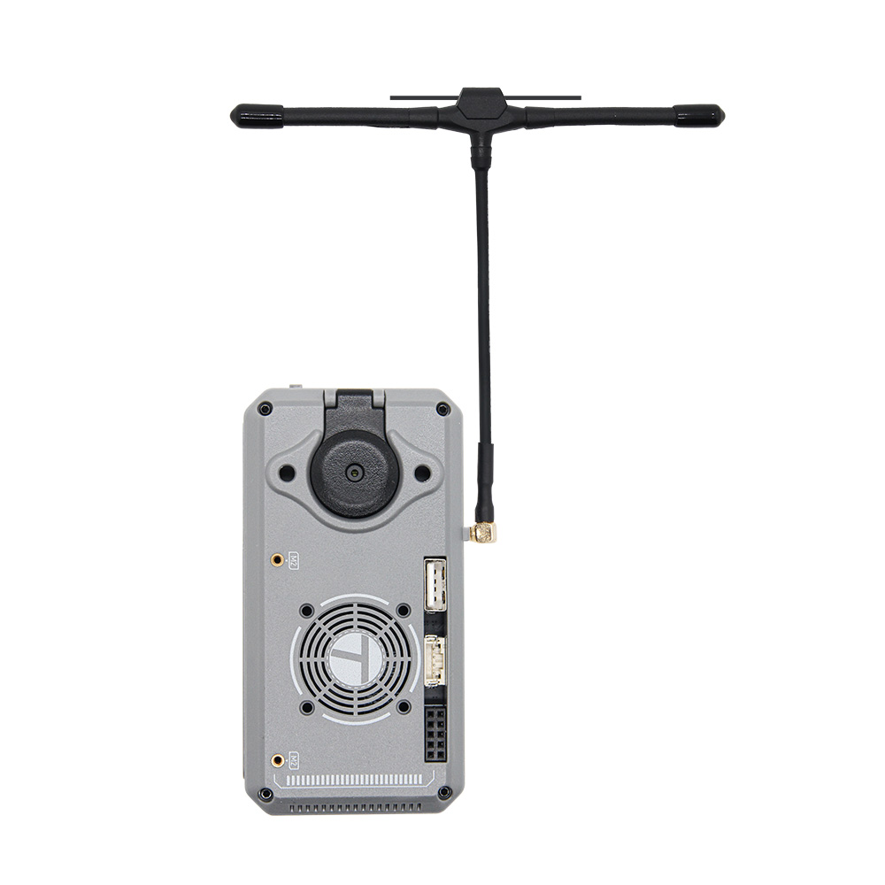
T-Display-CM0 is a handheld Linux development terminal built around a Raspberry Pi Compute Module 0 (CM0) with a 1 GHz quad-core 64-bit Arm Cortex-A53 processor and 512 MB LPDDR2 memory. It combines a 4.1-inch AMOLED touchscreen (568 × 1232, RM69A10 MIPI DSI) with a GT9895 capacitive touch controller, and supports an IMX219-AF camera with 180° rotation and audio. LR2021 LoRa is standard on every unit. Ethernet, HDMI, USB, and expansion connectors support desktop use, camera applications, and connected hardware projects.
The operating system is based on Raspberry Pi OS and includes a custom desktop environment. The factory firmware software is maintained in the LILYGO-UI organization. Detailed usage and development documentation will be published and updated on the LILYGO UI documentation site (Chinese). Kernel drivers and Device Tree Overlays are maintained in lilygo-linux-dtoverlays — T-DisplayCM0. Keyboard, battery, GNSS, and LTE-M functions depend on the installed expansion modules.
Quick Start
Power On
- Connect a 5 V power supply through either Type-C port.
- Press the POWER button for about 1 second to start the device.
For firmware flashing, application usage, and development instructions, see the LILYGO UI documentation site (Chinese).
Related Videos
Key Features
- Raspberry Pi Compute Module 0 (CM0): 1 GHz quad-core 64-bit Arm Cortex-A53 and 512 MB LPDDR2
- Operating system based on Raspberry Pi OS with a custom desktop environment
- LILYGO-UI factory firmware software, with Linux kernel driver and Device Tree Overlay sources
- 2.4 GHz 802.11 b/g/n Wireless LAN
- Bluetooth 4.2 standard with Bluetooth Low Energy (BLE) support
- 4.1-inch AMOLED display, 568 × 1232 resolution, RM69A10 MIPI DSI interface
- GT9895 capacitive multi-touch input
- IMX219-AF camera module with 180° rotation and MIPI CSI-2 interface
- ES8390 I2S audio codec
- LR2021 LoRa radio over SPI, standard on every unit
- QMI8658B IMU and RTC interfaces, plus charging and battery interfaces through the keyboard expansion module
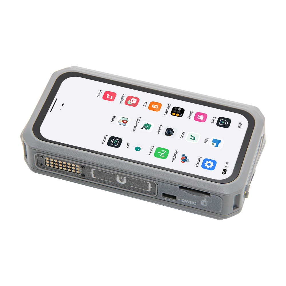
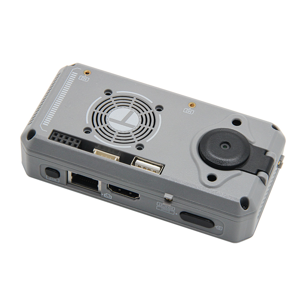
- Ethernet, HDMI output up to 1080p at 30 FPS, USB Type-A, Type-C, and TF card slot
- 3 × 8 keyboard expansion contacts, QWIIC 4-pin, Grove 4-pin, and two I2C buses
- Expansion support for keyboard, batteries, GNSS, and LTE-M
Specifications
| Parameter | Value |
|---|---|
| Platform | Raspberry Pi Compute Module 0 (CM0) |
| Processor | 1 GHz quad-core 64-bit Arm Cortex-A53 |
| Memory | 512 MB LPDDR2 |
| Wireless | 2.4 GHz band, 802.11 b/g/n Wireless LAN |
| Bluetooth | Bluetooth 4.2 standard with Bluetooth Low Energy (BLE) support |
| Operating system | Based on Raspberry Pi OS with a custom desktop environment; factory firmware software maintained by LILYGO-UI |
| Display | 4.1-inch AMOLED, 568 × 1232, RM69A10, MIPI DSI |
| Touch | Goodix GT9895, I2C, address 0x5D |
| Camera | IMX219-AF, MIPI CSI-2, 180° rotation |
| Audio | ES8390, I2S; I2C control address 0x11 |
| LoRa | LR2021, SPI; standard on every unit |
| IMU | QMI8658B, I2C address 0x6A |
| RTC | RX8130CE, I2C address 0x32 |
| Charging management | BQ25896 on the keyboard expansion module, I2C address 0x6B |
| Battery gauge | BQ27220 on the keyboard expansion module, I2C address 0x55 |
| I/O expander | XL9555, I2C address 0x26 |
| Keyboard expansion | TCA8418 controller on the keyboard expansion module, 7 × 10 matrix, I2C address 0x34 |
| Storage | TF / microSD card; CM0 Lite has no onboard eMMC |
| Video output | HDMI, 1080p at 30 FPS |
| Wired network | Ethernet |
| USB | Type-A; two Type-C ports support 5 V input |
| Expansion connectors | 3 × 8 keyboard contacts, QWIIC 4-pin, Grove 4-pin, rear header |
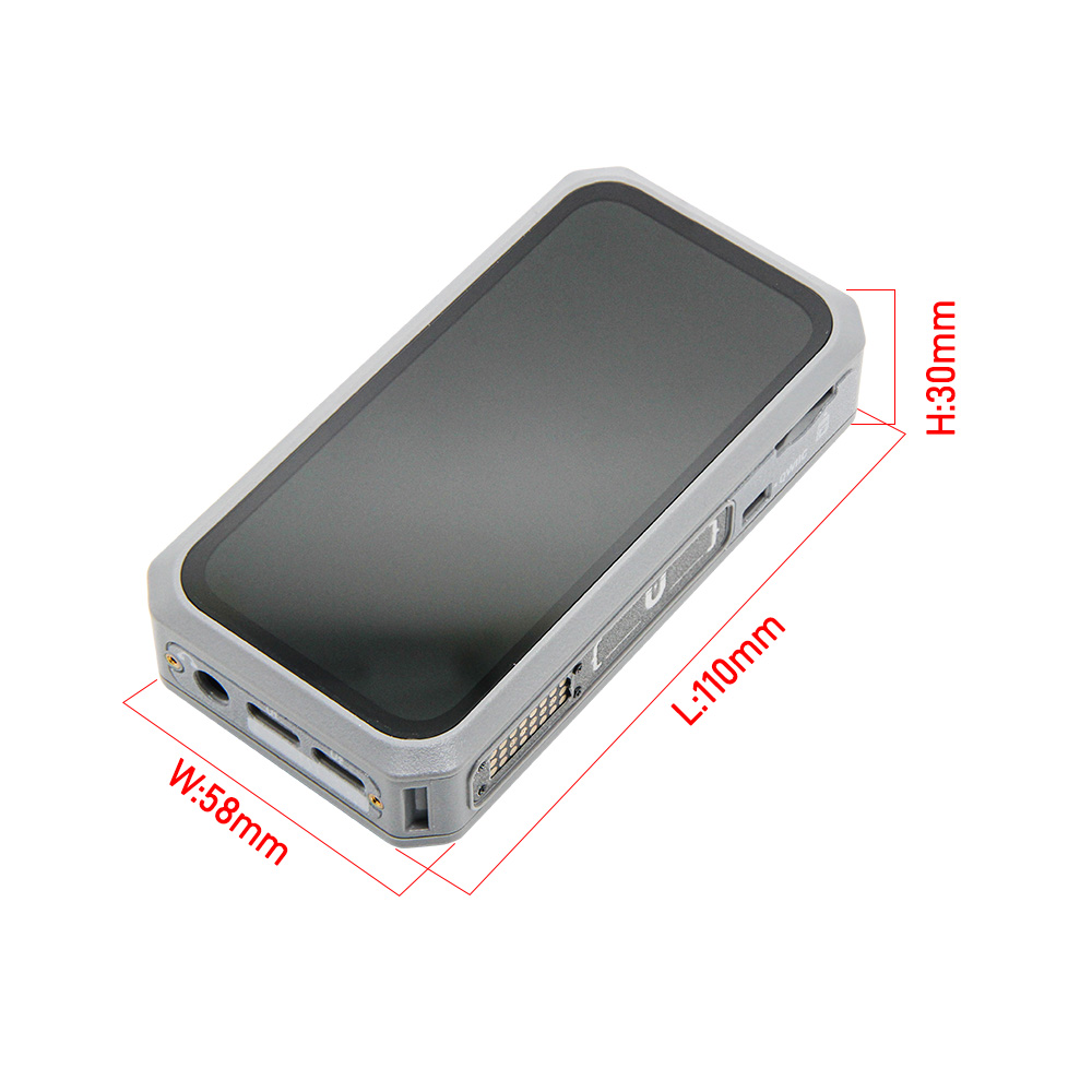
| Enclosure dimensions | 110 × 58 × 30 mm (L × W × H), as shown in the supplied dimension drawing |
The BQ25896 charger, BQ27220 battery gauge, and TCA8418 keyboard controller are provided through the keyboard expansion module; they are not populated on the CM0 carrier board.
The supplied pin diagram and V0.3 schematic identify the audio codec as ES8390. The Linux board support documentation uses the es8389 driver name for ES8389 / ES8390 audio support. Match drivers and Overlays to your hardware revision; Expansion-module functions depend on the installed modules.
Pin Diagram
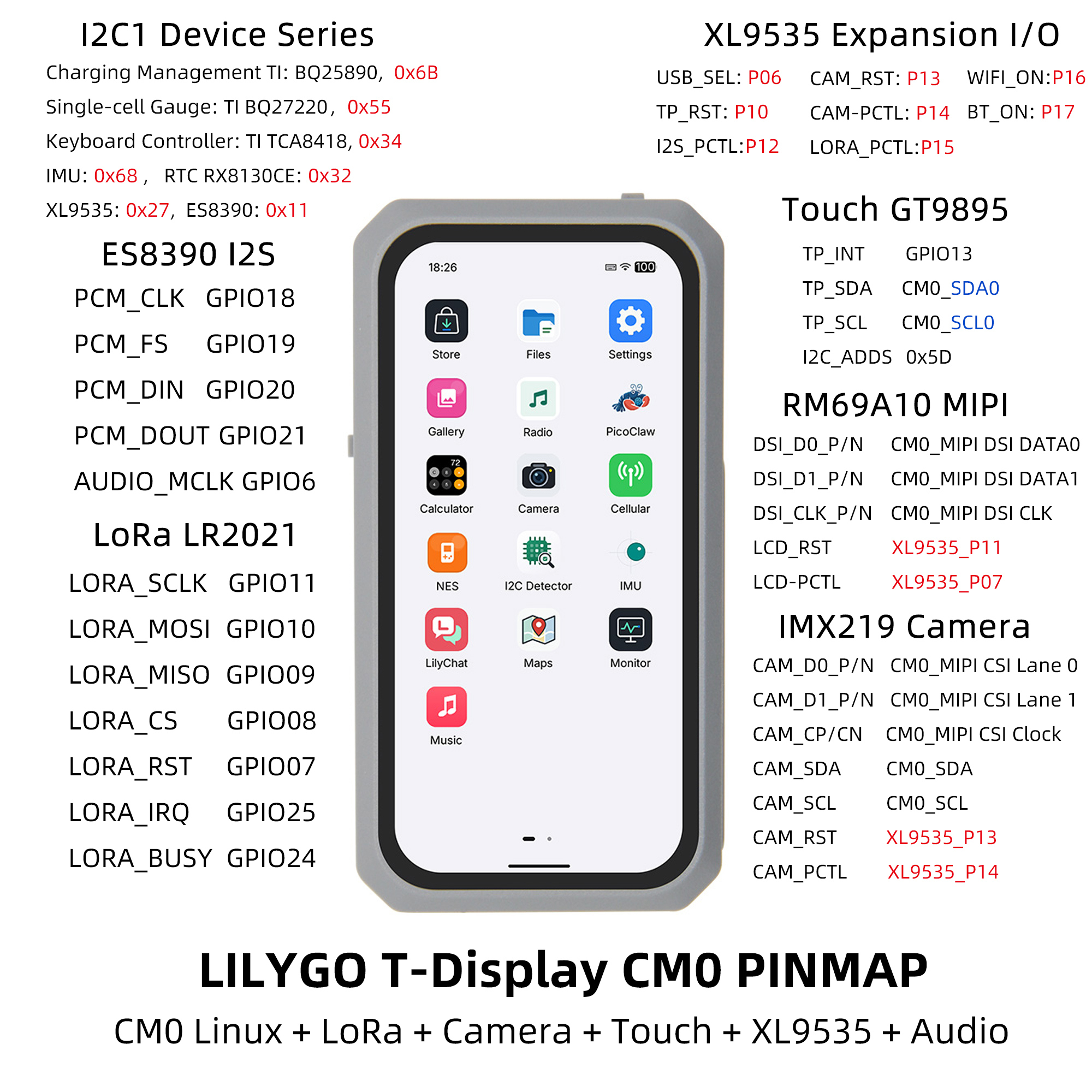
The mappings below follow the supplied product pin diagram. GPIO numbers refer to CM0 GPIO signals. XL9555 pins retain their Pxx port notation (for example, P11 means port 1, bit 1); they are not CM0 GPIO numbers. CM0_* names retain the signal labels used in the diagram.
Display
| RM69A10 | DSI Data 0 | DSI Data 1 | DSI Clock | RESET | Power EN |
|---|---|---|---|---|---|
| CM0 | CM0_MIPI DSI DATA0 | CM0_MIPI DSI DATA1 | CM0_MIPI DSI CLK | ||
| XL9555 | P11 | P07 |
Touch
| GT9895 | SDA | SCL | INT | RESET |
|---|---|---|---|---|
| CM0 | CM0_SDA0 | CM0_SCL0 | GPIO13 | |
| XL9555 | P10 |
Audio
| ES8390 | PCM_CLK | PCM_FS | PCM_DIN | PCM_DOUT | AUDIO_MCLK | Power EN |
|---|---|---|---|---|---|---|
| CM0 | GPIO18 | GPIO19 | GPIO20 | GPIO21 | GPIO6 | |
| XL9555 | P12 |
LoRa
| LR2021 | SCK | MOSI | MISO | CS | RESET | INT | BUSY | Power EN |
|---|---|---|---|---|---|---|---|---|
| CM0 | GPIO11 | GPIO10 | GPIO9 | GPIO8 | GPIO7 | GPIO25 | GPIO24 | |
| XL9555 | P15 |
Camera
| IMX219-AF | CSI Lane 0 | CSI Lane 1 | CSI Clock | SDA | SCL | RESET | Power EN |
|---|---|---|---|---|---|---|---|
| CM0 | CM0_MIPI CSI Lane 0 | CM0_MIPI CSI Lane 1 | CM0_MIPI CSI Clock | CM0_SDA | CM0_SCL | ||
| XL9555 | P13 | P14 |
I2C1 Devices
The CM0 carrier board does not populate the BQ25896, BQ27220, or TCA8418. These devices and addresses are available through the keyboard expansion module when it is connected.
| Device | Address |
|---|---|
| BQ25896 charging management (keyboard expansion module) | 0x6B |
| BQ27220 battery gauge (keyboard expansion module) | 0x55 |
| TCA8418 keyboard controller (keyboard expansion module) | 0x34 |
| QMI8658B IMU | 0x6A |
| RX8130CE RTC | 0x32 |
| XL9555 I/O expander | 0x26 |
| ES8390 audio codec | 0x11 |
USB and Wireless Control
| Control | USB_SEL | WIFI_ON | BT_ON |
|---|---|---|---|
| XL9555 | P06 | P16 | P17 |
Expansion Connectors
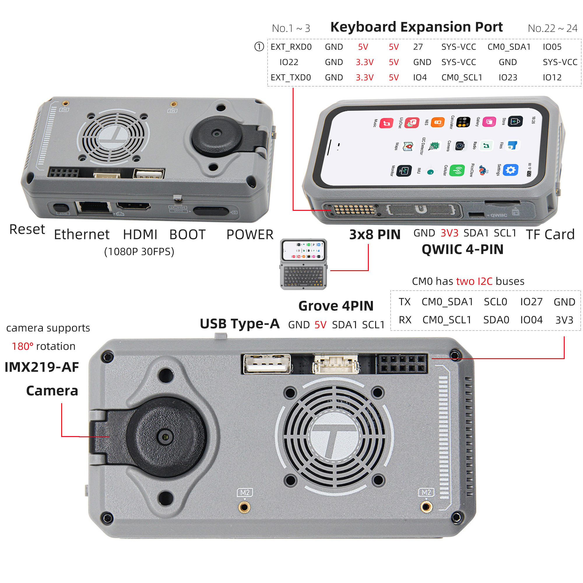
The diagram shows connector orientation and the keyboard contact layout. Preserve that orientation when wiring; the QWIIC and Grove connectors expose different supply voltages.
| Connector | Signals shown in the diagram |
|---|---|
| QWIIC 4-pin | GND, 3V3, SDA1, SCL1 |
| Grove 4-pin | GND, 5V, SDA1, SCL1 |
| Rear header, upper row | TX, CM0_SDA1, SCL0, GPIO27, GND |
| Rear header, lower row | RX, CM0_SCL1, SDA0, GPIO4, 3V3 |
| Keyboard expansion | 3 × 8 contacts; signal and power layout shown above |
Dimensions
Packing List
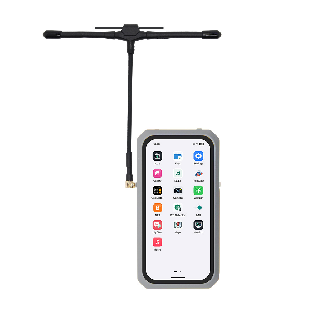
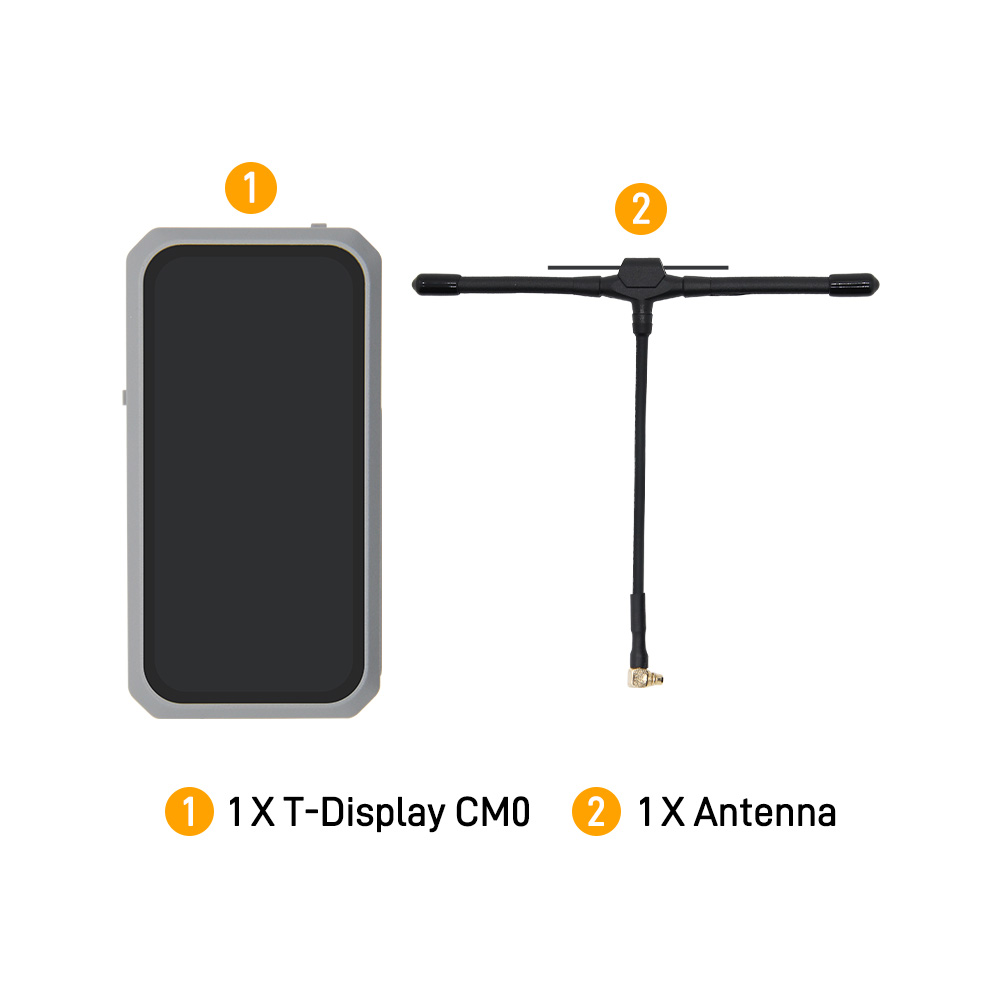
The supplied packing illustration shows 1 × T-Display-CM0 and 1 × antenna. Check the selected product option for the included modules and accessories.
Schematic
The complete schematic set consists of the following three PDFs:
- T-DIsplay-CM0-V0.3-20260815.pdf (main board)
- T-DIsplay-CM0_SUB-V0.3-20260818.pdf (SUB board)
- T-DIsplay-CM0_FPC-V0.3-20260818.pdf (FPC)
Datasheet
- CM0 + CM0-KIT Chinese specifications
- LR20xx datasheet (V2.2)
- H0410S001AMT001 4.1-inch AMOLED specifications (568 × 1232, MIPI)
- GT9895 touch controller (V1.1)
- IMX219PQH5 image sensor
- ES8390 audio codec
- QMI8658B IMU
- RX8130CE RTC
- XL9555 I/O expander
- GEK100 power on/off controller
- BQ25896 charging management (keyboard expansion module)
- BQ27220 battery gauge (keyboard expansion module)
- TCA8418 keyboard controller (keyboard expansion module)
Software Libraries
Factory Firmware Software
The software associated with the factory firmware is maintained under LILYGO-UI. Visit the organization for the custom desktop environment, applications, shared libraries, and build tools; follow each repository's README for its build requirements.
Usage and Development Documentation
Detailed user guides and development documentation will be published and updated on the LILYGO UI documentation site (Chinese).
Kernel Drivers and Device Tree Overlays
Use lilygo-linux-dtoverlays — boards/T-DisplayCM0 for board support, Device Tree Overlays, and build and installation instructions. The board directory provides the build entry point; reusable external kernel driver sources are in the repository's modules/ directory.
Build kernel modules against the source or headers and configuration of the kernel running on the target device. Use the board README for the matching build parameters and boot configuration.
FAQ
Where can I find factory firmware software and documentation?
The software is maintained by LILYGO-UI. Detailed usage and development guides will be published and updated on the LILYGO UI documentation site (Chinese).
Why does a driver report Invalid module format?
The kernel module does not match the running kernel. Rebuild it against the target kernel's version and configuration, following the T-DisplayCM0 kernel driver instructions.
Does every device include LoRa, GNSS, and LTE-M?
Every T-Display-CM0 includes LR2021 LoRa as standard. GNSS, LTE-M, keyboard, and battery functionality depends on the fitted expansion modules. Check your selected hardware configuration before using the corresponding applications.
Changelog
| Version | Date | Notes |
|---|---|---|
| V0.3 main board schematic | 2026-08-15 | Date in the supplied PDF filename |
| V0.3 SUB and FPC schematics | 2026-08-18 | Date in the supplied PDF filenames |