T3-STM32 get it now
Overview
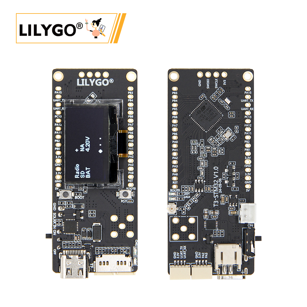
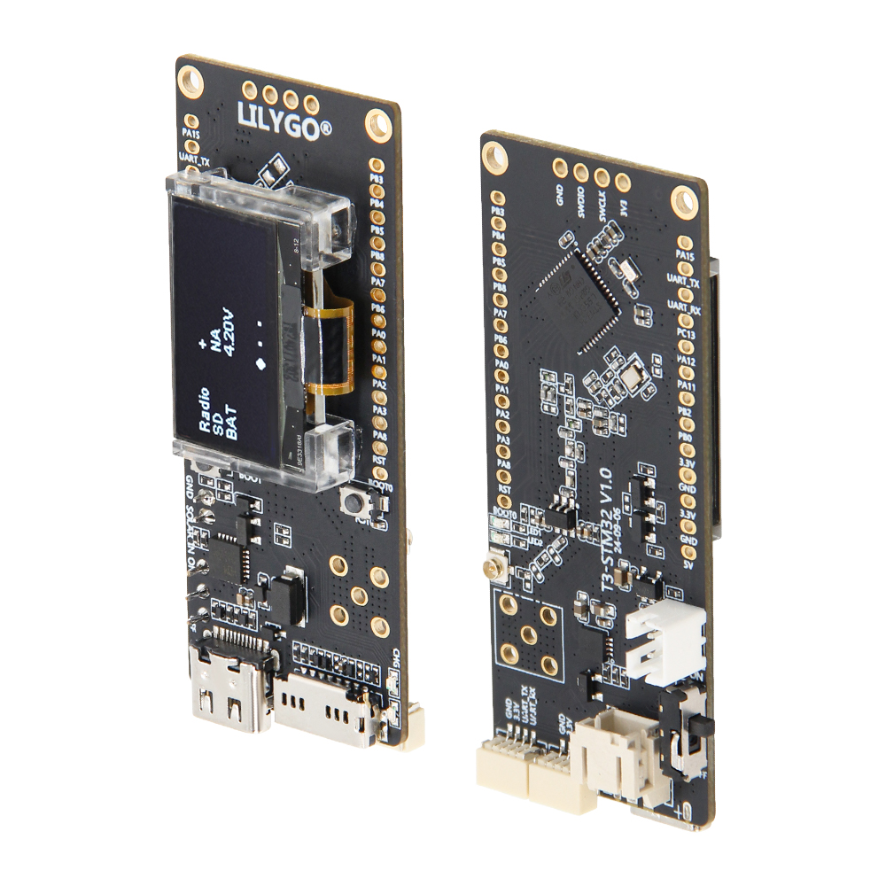
LILYGO T3-STM32 is a versatile IoT development board based on the STM32WL55CCU6 dual-core (Cortex-M4 + Cortex-M0+) low-power microcontroller with a built-in Sub-GHz radio (LoRa, FSK, BPSK). Supports 433/868/915 MHz multi-band LoRa for global deployment. Hardware includes 256 KB Flash, 64 KB SRAM, a 0.96-inch SSD1315 OLED (I2C), TF card slot (SPI), solar input (4.4–6 V), SWD debug interface, and QWIIC connectors. Suitable for remote monitoring, environmental sensing, LoRa gateways, and solar-powered IoT terminals.
Quick Start
Example Support
| Example | PlatformIO/Arduino | ESP-IDF | Description |
|---|---|---|---|
| T3-STM32 | ✓ | LED, OLED, SD card, SubGHz LoRa, deep sleep examples |
Available examples
├── 1_led                  # Basic LED blink
├── 2_jlink_rtt_print      # J-Link RTT debug output
├── 3_sdcard               # TF card test
├── 4_oled                 # OLED display
├── 5_RF_test              # AT Slave for RF testing
├── 6_SubGHz_TXRX          # LoRa TX/RX test
├── DeepSleep              # Deep sleep power test
└── PingPong               # SubGHz Phy PingPong
STM32CubeIDE
- Install STM32CubeIDE
- Install STM32CubeProgrammer
- Install debugger driver: ST-Link or J-Link
- Connect the debugger to the board's 4-pin SWD interface
- Open the project in STM32CubeIDE, compile and flash
PlatformIO
- Install Visual Studio Code and Python
- Search for and install the PlatformIO IDE extension in VS Code
- Open the
T3-STM32project folder - Open
platformio.ini, uncomment the example under[platformio] - Connect the debugger, click ✓ to compile, click → to upload
Development Platforms
Video
Key Features
- STM32WL55CCU6 dual-core Cortex-M4 + Cortex-M0+, built-in Sub-GHz radio
- LoRa (433/868/915 MHz) + FSK, GFSK, BPSK modulation
- 256 KB Flash + 64 KB SRAM
- 0.96-inch SSD1315 OLED (128 × 64), I2C
- TF card slot (SPI), solar input (4.4–6 V)
- 4-pin SWD debug interface
- 2 × QWIIC, 2.54mm 2×13 GPIO expansion
Product Parameters
| Feature | Specification |
|---|---|
| MCU | STM32WL55CCU6 @ Dual-core Cortex-M4 + M0+ |
| Flash | 256 KB |
| SRAM | 64 KB |
| Built-in Radio | LoRa, (G)FSK, (G)MSK, BPSK |
| LoRa Frequency | 433 / 868 / 915 MHz |
| Display | 0.96-inch SSD1315 OLED, 128 × 64, I2C |
| Storage | TF card slot (SPI) |
| USB | 1 × Type-C |
| Solar Input | 4.4–6 V |
| Debug | 4-pin SWD interface |
| Expansion | 2 × QWIIC, 2.54mm 2×13 GPIO |
| Antenna | LoRa antenna interface + 5-pin antenna socket |
| Buttons | RESET + BOOT |
| Mounting Holes | 2 × M2 |
| Dimensions | 66 × 27 × 13 mm |
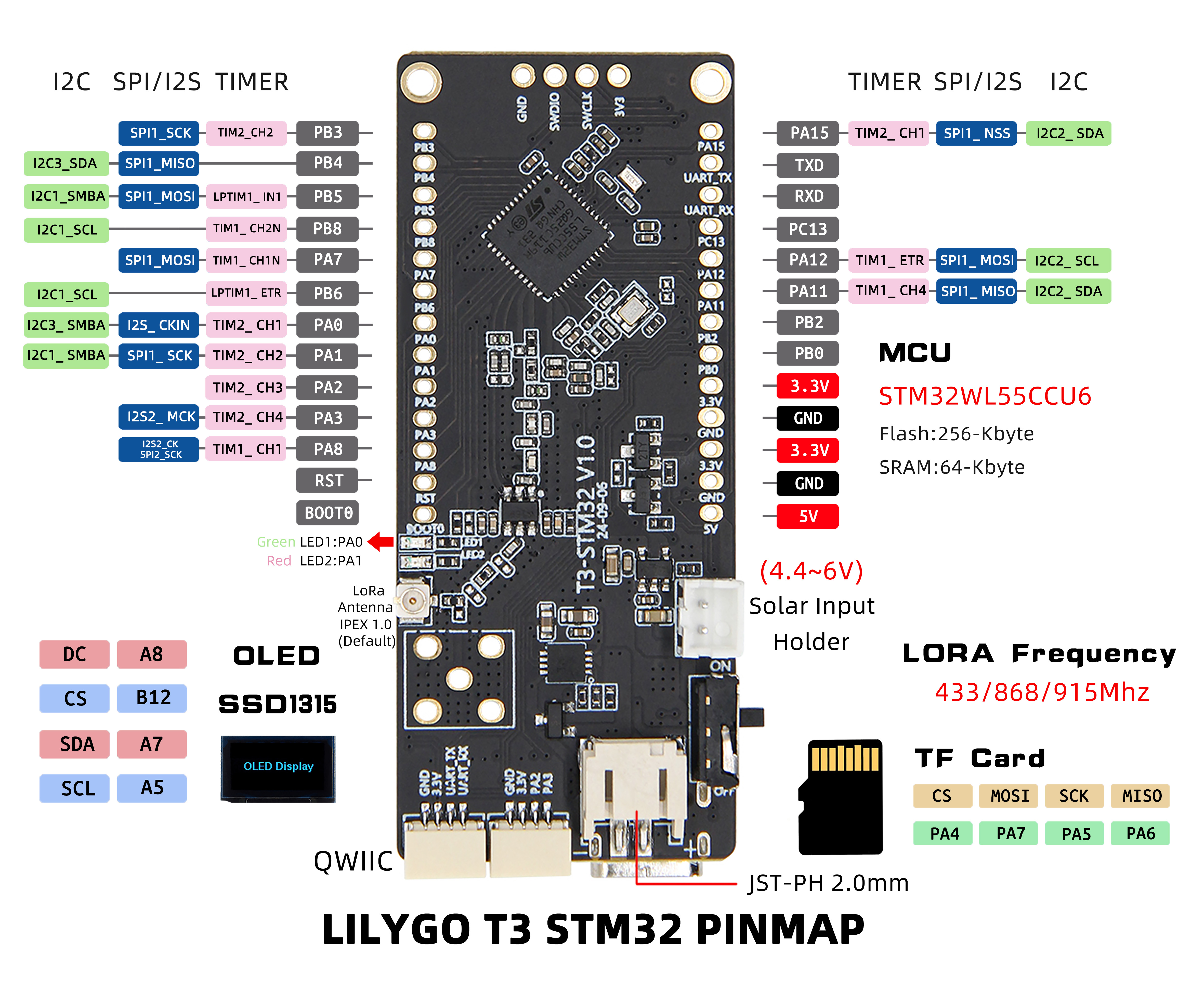
Pin Diagram
Dimension Diagram
Schematic
Datasheet
Software Development
Dependent Libraries
FAQ
Q. Which debuggers are supported? A. Supports ST-Link and J-Link, connected via the 4-pin SWD interface.
Q. What are the solar input requirements? A. Supports 4.4–6 V solar input, suitable for outdoor energy harvesting applications.
Q. How to select LoRa frequency band? A. Three frequency versions are available: 433 MHz, 868 MHz, 915 MHz. Select per regional regulations.
Version History
| Version | Release Date | Update Description |
|---|---|---|
| T3-STM32_V1.0 | 2024-07-30 | Initial hardware version |