T-Deck get it now
Overview
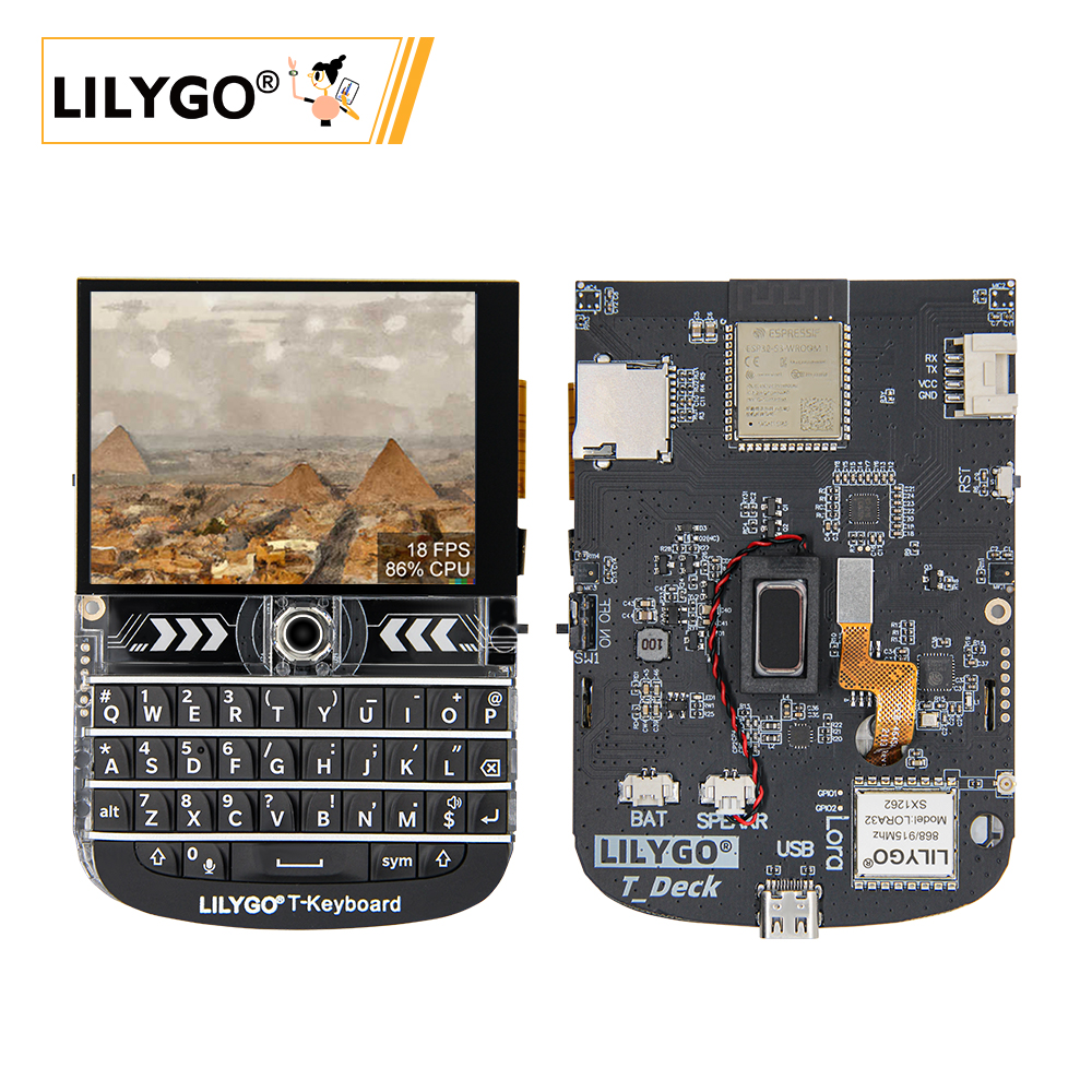
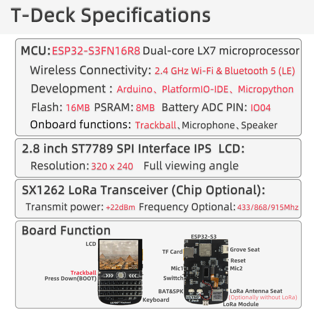
LILYGO T-Deck is a highly integrated multi-functional embedded development platform based on the ESP32-S3 main control chip. It integrates a 2.8-inch ST7789 LCD (320 × 240), trackball navigation module, physical keyboard (I²C), TF card storage, LoRa SX1262 wireless module, and ES7210 microphone array. Suitable for IoT terminals, portable interactive devices, and low-power wireless communication projects.
Notes:
- T-Deck-Plus has allocated the Grove interface pins for GPS module use — the Grove interface on T-Deck-Plus cannot be used as a general-purpose interface.
- T-Deck updated the TFT_eSPI ST7789 initialization sequence on 2024-07-26. If you encounter incorrect screen display, check that the initialization sequence in the repo matches.
- The LoRa radio module shares the SPI bus with other peripherals. Only one SPI device can be selected at a time — ensure all other SPI device CS lines are high (inactive) before communicating with the SX1262.
- When powered by battery, GPIO10 must be set HIGH. This requirement can be ignored when the board is powered via USB.
Quick Start
Example Support
| Example | PlatformIO/Arduino | ESP-IDF | Description |
|---|---|---|---|
| T-Deck Examples | ✓ | Keyboard, Microphone, GPS, Touchpad, Unit Test |
Available examples:
├─Keyboard_ESP32C3       # ESP32C3 keyboard I2C slave
├─Keyboard_T_Deck_Master # T-Deck read from keyboard
├─Microphone             # Noise detection
├─Touchpad               # Read touch coordinates
├─GPSShield              # GPS Shield example
└─UnitTest               # Factory hardware unit testing
If microphone is enabled, the middle trackball button (GPIO0) is not available.
PlatformIO
- Install Visual Studio Code and Python
- Search for and install the PlatformIO IDE extension in VS Code
- After restarting VS Code, click File → Open Folder → select the
T-Deckdirectory - Open
platformio.ini, uncomment the example you want to use (only one active at a time) - Click ✓ to compile, connect via USB, click → to upload
Arduino
- Install Arduino IDE
- Copy all folders from
T-Deck/libto your Arduino libraries folder - In Tools → Board, configure:
| Arduino IDE Setting | Value |
|---|---|
| Board | ESP32S3 Dev Module |
| USB CDC On Boot | Enable |
| CPU Frequency | 240 MHz |
| USB DFU On Boot | Disable |
| Flash Mode | QIO 80 MHz |
| Flash Size | 16MB(128Mb) |
| USB Firmware MSC On Boot | Disable |
| PSRAM | OPI PSRAM |
| Partition Scheme | 16M Flash(3MB APP/9.9MB FATFS) |
| USB Mode | Hardware CDC and JTAG |
| Upload Mode | UART0/Hardware CDC |
| Upload Speed | 921600 |
- Click Upload. If upload fails, hold the BOOT button (trackball center), insert USB, then click Upload. After upload, click RST to exit download mode.
The ESP32C3 programming interface is the 6-pin header near the RST button (top to bottom: 3V3, GND, RST, BOOT, RX, TX).
Development Platforms
Video
Key Features
- ESP32-S3FN16R8 dual-core LX7 @ 240 MHz, Wi-Fi + Bluetooth 5.0 LE
- SX1262 LoRa (433–915 MHz, optional)
- MIA-M10Q GNSS module
- 2.8-inch ST7789 LCD (320 × 240), no touch — trackball navigation
- Physical keyboard (I²C communication)
- ES7210 audio codec + MSM381A3729H9CP microphone array
- 2000 mAh lithium polymer battery
- 16 MB Flash + 8 MB PSRAM + TF card slot
Product Parameters
| Feature | Specification |
|---|---|
| MCU | ESP32-S3FN16R8 @ Dual-core LX7, 240 MHz |
| Flash | 16 MB |
| PSRAM | 8 MB |
| Wi-Fi | 2.4 GHz 802.11 b/g/n |
| Bluetooth | Bluetooth 5.0 LE |
| LoRa | SX1262, 433–915 MHz (optional) |
| GPS | MIA-M10Q GNSS |
| Display | 2.8-inch ST7789 LCD, 320 × 240 |
| Input | Trackball + physical keyboard (I²C) |
| Audio | ES7210 codec + microphone array |
| Battery | 2000 mAh lithium polymer |
| Storage | TF card expansion |
| USB | 1 × Type-C |
| Dimensions | 100 × 68 × 11 mm |
Pin Diagram
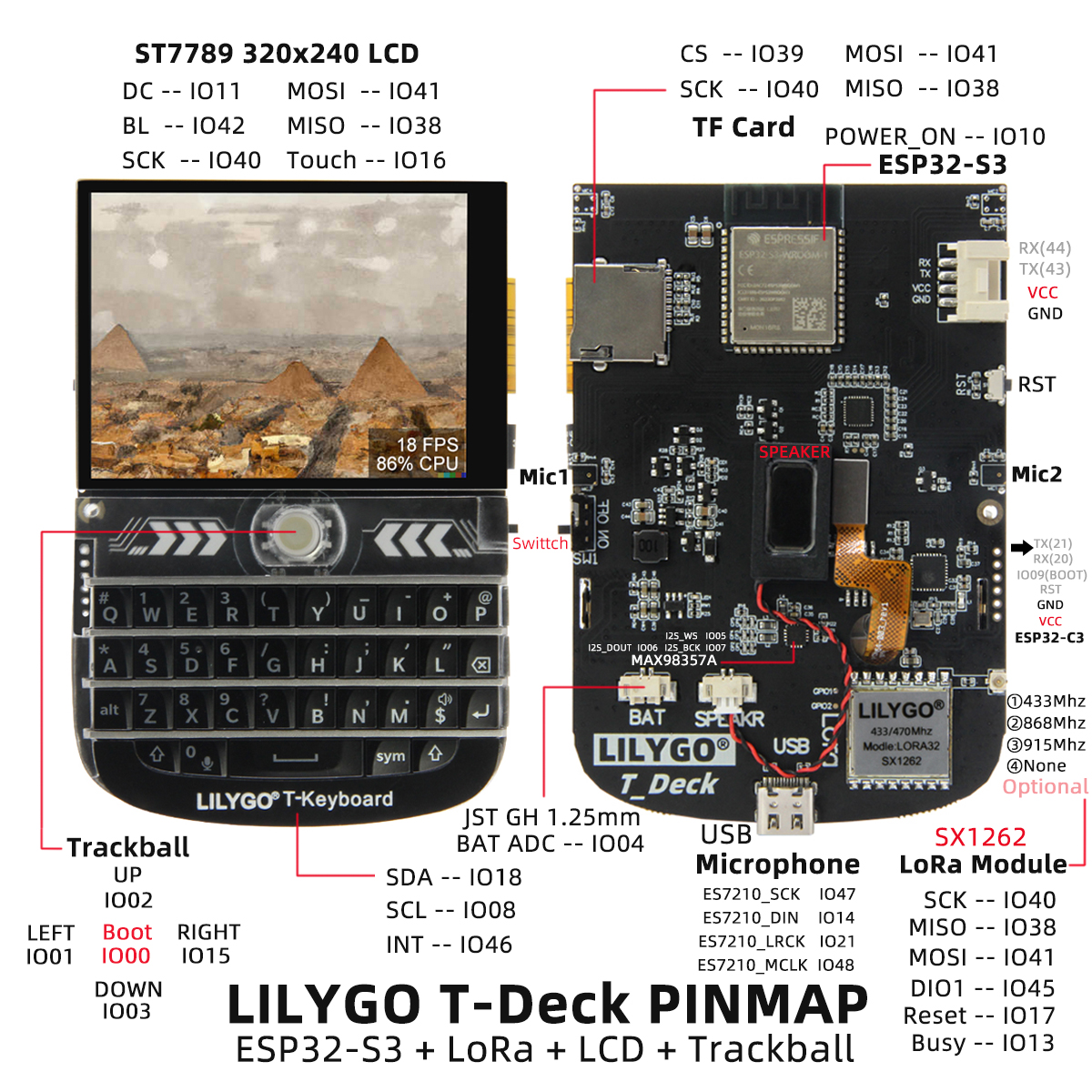
Pin Mapping
| Signal | GPIO |
|---|---|
| Power Enable | 10 |
| I2S WS | 5 |
| I2S BCK | 7 |
| I2S DOUT | 6 |
| I2C SDA | 18 |
| I2C SCL | 8 |
| Battery ADC | 4 |
| Touch INT | 16 |
| Keyboard INT | 46 |
| SD CS | 39 |
| TFT CS | 12 |
| LoRa CS | 9 |
| TFT DC | 11 |
| TFT Backlight | 42 |
| SPI MOSI | 41 |
| SPI MISO | 38 |
| SPI SCK | 40 |
| Trackball G01 | 3 |
| Trackball G02 | 2 |
| Trackball G03 | 15 |
| Trackball G04 | 1 |
| ES7210 MCLK | 48 |
| ES7210 LRCK | 21 |
| ES7210 SCK | 47 |
| ES7210 DIN | 14 |
| LoRa BUSY | 13 |
| LoRa RST | 17 |
| LoRa DIO1 | 45 |
| BOOT | 0 |
| GPS TX | 43 |
| GPS RX | 44 |
Peripheral Initialization
The following snippets show the minimum setup for each peripheral using the pin definitions above. Copy the #define block from Pin Mapping into your sketch, then use the relevant snippet.
Before any SPI transaction — pull all other CS lines HIGH first:
cppdigitalWrite(BOARD_SDCARD_CS, HIGH); digitalWrite(BOARD_TFT_CS, HIGH); digitalWrite(RADIO_CS_PIN, HIGH);
Power Enable (battery-powered builds)
// Must be set HIGH when running on battery; safe to call on USB too.
pinMode(BOARD_POWERON, OUTPUT);
digitalWrite(BOARD_POWERON, HIGH);
Display (ST7789 — Arduino_GFX)
#include <Arduino_GFX_Library.h>

Arduino_DataBus *bus = new Arduino_ESP32SPI(
    BOARD_TFT_DC, BOARD_TFT_CS,
    BOARD_SPI_SCK, BOARD_SPI_MOSI, BOARD_SPI_MISO);

// 320×240, no RST pin (-1), portrait
Arduino_GFX *gfx = new Arduino_ST7789(bus, -1, 0, true, 320, 240);

void setup() {
    pinMode(BOARD_TFT_BACKLIGHT, OUTPUT);
    digitalWrite(BOARD_TFT_BACKLIGHT, HIGH);
    gfx->begin();
    gfx->fillScreen(BLACK);
}
Display (ST7789 — TFT_eSPI)
Requires
User_Setup.hconfigured for T-Deck — see the 2024-07-26 commit for the correct initialization sequence.
#include <TFT_eSPI.h>

TFT_eSPI tft;

void setup() {
    pinMode(BOARD_TFT_BACKLIGHT, OUTPUT);
    digitalWrite(BOARD_TFT_BACKLIGHT, HIGH);
    tft.init();
    tft.setRotation(1);
    tft.fillScreen(TFT_BLACK);
}
LoRa (SX1262 — RadioLib)
#include <RadioLib.h>

SX1262 radio = new Module(
    RADIO_CS_PIN,   // CS
    RADIO_DIO1_PIN, // DIO1 / IRQ
    RADIO_RST_PIN,  // RST
    RADIO_BUSY_PIN  // BUSY
);

void setup() {
    // Deselect other SPI devices first
    pinMode(BOARD_SDCARD_CS, OUTPUT); digitalWrite(BOARD_SDCARD_CS, HIGH);
    pinMode(BOARD_TFT_CS,    OUTPUT); digitalWrite(BOARD_TFT_CS,    HIGH);

    SPI.begin(BOARD_SPI_SCK, BOARD_SPI_MISO, BOARD_SPI_MOSI);

    // 915.0 MHz, +22 dBm, bandwidth 125 kHz, SF7, CR 4/5
    int state = radio.begin(915.0);
    if (state != RADIOLIB_ERR_NONE) {
        Serial.printf("LoRa init failed: %d\n", state);
    }
}
Keyboard (I²C)
#include <Wire.h>

#define KEYBOARD_ADDR 0x55

void setup() {
    Wire.begin(BOARD_I2C_SDA, BOARD_I2C_SCL);
    pinMode(BOARD_KEYBOARD_INT, INPUT_PULLUP);
}

// Poll or use interrupt — read one byte per keypress
void loop() {
    if (digitalRead(BOARD_KEYBOARD_INT) == LOW) {
        Wire.requestFrom(KEYBOARD_ADDR, 1);
        if (Wire.available()) {
            char key = Wire.read();
            Serial.printf("Key: %c\n", key);
        }
    }
}
Trackball
// Trackball outputs quadrature pulses on four GPIOs.
// Attach interrupts to detect movement direction.
void setup() {
    pinMode(BOARD_TBOX_G01, INPUT);
    pinMode(BOARD_TBOX_G02, INPUT);
    pinMode(BOARD_TBOX_G03, INPUT);
    pinMode(BOARD_TBOX_G04, INPUT);
}
Microphone (ES7210 — I²S)
When the microphone is enabled, GPIO0 (BOOT / trackball center button) is not available.
#include <driver/i2s.h>

void setup() {
    i2s_config_t i2s_config = {
        .mode = (i2s_mode_t)(I2S_MODE_MASTER | I2S_MODE_RX),
        .sample_rate = 16000,
        .bits_per_sample = I2S_BITS_PER_SAMPLE_16BIT,
        .channel_format = I2S_CHANNEL_FMT_RIGHT_LEFT,
        .communication_format = I2S_COMM_FORMAT_STAND_I2S,
        .intr_alloc_flags = ESP_INTR_FLAG_LEVEL1,
        .dma_buf_count = 4,
        .dma_buf_len = 256,
        .use_apll = false,
    };
    i2s_pin_config_t pin_config = {
        .mck_io_num   = BOARD_ES7210_MCLK,
        .bck_io_num   = BOARD_ES7210_SCK,
        .ws_io_num    = BOARD_ES7210_LRCK,
        .data_in_num  = BOARD_ES7210_DIN,
        .data_out_num = I2S_PIN_NO_CHANGE,
    };
    i2s_driver_install(I2S_NUM_0, &i2s_config, 0, NULL);
    i2s_set_pin(I2S_NUM_0, &pin_config);
}
SD Card (SPI)
#include <SD.h>

void setup() {
    SPI.begin(BOARD_SPI_SCK, BOARD_SPI_MISO, BOARD_SPI_MOSI);
    if (!SD.begin(BOARD_SDCARD_CS)) {
        Serial.println("SD init failed");
    }
}
Dimension Diagram
Schematic
Datasheet
Software Development
Dependent Libraries
FAQ
Q. Still don't know how to set up the programming environment? A. Refer to the LilyGo-Document for additional setup instructions.
Q. Arduino IDE prompts to upgrade library files — should I? A. Do not upgrade. Different library versions may be incompatible; stay with the versions in the
libdirectory.Q. Does T-Deck have a touch screen? A. No. T-Deck uses a trackball navigation module instead of a touch screen.
Q. Upload keeps failing? A. Hold the trackball center button (BOOT), then insert USB, then click Upload. After completion, press RST to exit download mode.
Version History
| Version | Release Date | Update Description |
|---|---|---|
| V1.0 | — | Initial release |