T-Display-S3 get it now
Overview
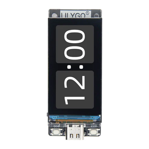
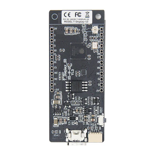
T-Display-S3 is a development board whose main control chip is ESP32-S3. It is equipped with a 1.9-inch LCD color screen and two programmable buttons. Communication using the I8080 interface Retains the same layout design as T-Display. You can directly use ESP32S3 for USB communication or programming.
Quick Start
Example Support
| Example | PlatformIO/Arduino | ESP-IDF | Description |
|---|---|---|---|
| T-Display-S3 | ✓ | ✓ | BLE, WIFI, SPIFFS, FFat examples |
PlatformIO
- Install Visual Studio Code and Python
- Search for the PlatformIO plugin in the VisualStudioCode extension and install it.
- After the installation is complete, you need to restart VisualStudioCode
- After restarting VisualStudioCode, select File in the upper left corner of VisualStudioCode -> Open Folder -> select the T-Display-S3 directory
- Wait for the installation of third-party dependent libraries to complete
- Click on the platformio.ini file, and in the platformio column
- Uncomment one of the lines default_envs = xxxx to make sure only one line works
- Click the (✔) symbol in the lower left corner to compile
- Connect the board to the computer USB
- Click (→) to upload firmware
- Click (plug symbol) to monitor serial output
- If it cannot be written, or the USB device keeps flashing, please check the FAQ below
Arduino
Install Arduino IDE
In Arduino Preferences, on the Settings tab, enter the https://raw.githubusercontent.com/espressif/arduino-esp32/gh-pages/package_esp32_index.json URL in the Additional boards manager URLs input box. Please pay attention to the version. The test phase is using 2.0.14. It is not certain that versions above 2.0.14 can run. When the operation is abnormal, please downgrade to a version below 2.0.14. , As of 2024/08/02, TFT_eSPI does not work on versions higher than 2.0.14, see TFT_eSPI/issue3329
Download T-Display-S3 , move to Arduino library folder (e.g. C:\Users\YourName\Documents\Arduino\libraries)
Copy all folders in lib folder to Arduino library folder (e.g. C:\Users\YourName\Documents\Arduino\libraries)
Enter the downloaded T-Display-S3/examples directory
Select any example and double-click the any_example.ino to open it
Select any example and double-click the
any_example.inoto open itOpen ArduinoIDE ,
Tools,Make your selection according to the table belowArduino IDE Setting Value Board ESP32S3 Dev Module Port Your port USB CDC On Boot Enable CPU Frequency 240MHZ(WiFi) Core Debug Level None USB DFU On Boot Disable Erase All Flash Before Sketch Upload Disable Events Run On Core1 Flash Mode QIO 80MHZ Flash Size 16MB(128Mb) Arduino Runs On Core1 USB Firmware MSC On Boot Disable Partition Scheme 16M Flash(3M APP/9.9MB FATFS) PSRAM OPI PSRAM Upload Mode UART0/Hardware CDC Upload Speed 921600 USB Mode CDC and JTAG - The options in bold are required, others are selected according to actual conditions.
Click
upload, Wait for compilation and writing to complete
ESP-IDF
T-Display-S3esp-idf version example, please jump to this LilyGo-Display-IDF
Micropython
Development Platforms
Video
Key Features
- ESP32-S3R8 Dual-core LX7 microprocessor
- Wi-Fi 802.11, BLE 5 + BT mesh
- 1.9" diagonal, Full-color TFT Display
- 170(H)RGB x320(V) 8-Bit Parallel Interface
- STEMMA QT / Qwiic
- JST-GH 1.25mm 2PIN
Product Parameters
| Feature | Specification |
|---|---|
| MCU | ESP32-S3R8 Dual-core LX7 microprocessor |
| Wireless Connectivity | Wi-Fi 802.11, BLE 5 + BT mesh |
| Programming Platform | Arduino-ide、 Micropython |
| Flash | 16MB |
| PSRAM | 8MB |
| Bat voltage detection | IO04 |
| Onboard functions | Boot + Reset + IO14 Button |
| LCD | 1.9" diagonal, Full-color TFT Display |
| Drive Chip | ST7789V |
| Resolution | 170(H)RGB x320(V) 8-Bit Parallel Interface |
| Working power supply | 3.3v |
| Support | STEMMA QT / Qwiic JST-SH 1.0mm 4-PIN |
| Connector | JST-GH 1.25mm 2PIN |
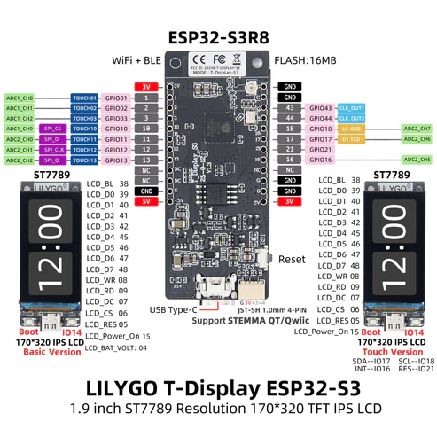
Pin Diagram
Display
| ST7789V | BL | Power EN | RST | CS | DC | WR | RD | D0 | D1 | D2 | D3 | D4 | D5 | D6 | D7 |
|---|---|---|---|---|---|---|---|---|---|---|---|---|---|---|---|
| ESP32-S3 | GPIO38 | GPIO15 | GPIO5 | GPIO6 | GPIO7 | GPIO8 | GPIO9 | GPIO39 | GPIO40 | GPIO41 | GPIO42 | GPIO45 | GPIO46 | GPIO47 | GPIO48 |
Button
| Button | BOOT | User |
|---|---|---|
| ESP32-S3 | GPIO0 | GPIO14 |
Battery
| Battery | ADC |
|---|---|
| ESP32-S3 | GPIO4 |
I2C (QWIIC / STEMMA QT)
| I2C | SDA | SCL |
|---|---|---|
| ESP32-S3 | GPIO18 | GPIO17 |
UART
| UART | TX | RX |
|---|---|---|
| ESP32-S3 | GPIO43 | GPIO44 |
Dimension Diagram
Schematic
Datasheet
Software Development
Dependent Libraries
FAQ
- The screen does not light up when using battery?
- When T-Display-S3 is powered by battery, GPIO15 must be set to HIGH to turn on the backlight.
- Please add the following two lines at the beginning of the setup
C++void setup(){ //Turn on display power pinMode(15, OUTPUT); digitalWrite(15, HIGH); } - The program can be written normally, but there is still no display after writing
- If you are using TFT_eSPI, then you can try running
Arduino_GFXDemofirst. If nothing is displayed after writing, you can determine that there is a problem with the hardware. - If
Arduino_GFXDemois written normally, but TFT_eSPI is not displayed, then it can be judged thatUser_Setup_Selecthas been overwritten, then please read the third article of FAQ to reconfigure TFT_eSPI
How to update TFT_eSPI, or confirm whether the TFT_eSPI pin configuration is correct?
- Search for TFT_eSPI in the ArduinoIDE library manager and click Update.
- Enter the default library manager installation location and open the TFT_eSPI folder. The default installation location is:(e.g. C:\Users\YourName\Documents\Arduino\libraries)
- Open User_Setup_Select.h, comment out #include <User_Setup.h> which is enabled by default, or delete it
- Search Setup206_LilyGo_T_Display_S3, find it, cancel the previous comment, then save it, and finally close it, so that TFT_eSPI uses the pin definition of T-Display-S3 by default
c++#include <User_Setups/Setup206_LilyGo_T_Display_S3.h> // For the LilyGo T-Display S3 based ESP32S3 with ST7789 170 x 320 TFTCan't upload any sketch,Please enter the upload mode manually.
- Connect the board via the USB cable
- Press and hold the BOOT button , While still pressing the BOOT button
- Press RST button
- Release the RST button
- Release the BOOT button (If there is no BOOT button, disconnect IO0 from GND.)
- Upload sketch
- Press the RST button to exit download mode
If you use external power supply instead of USB-C, please turn off the CDC option. This is because the board will wait for USB access when it starts.
- For Arduino IDE users, it can be turned off in the options , Please note that turning off USB CDC will turn off Serial redirection to USBC. At this time, you will not see any Serial message output when opening the port from USB-C, but output from GPIO43 and GPIO44.
cTools -> USB CDC On Boot -> Disable- For platformio users, you can add the following compilation flags in the ini file
cbuild_flags = ; Enable -DARDUINO_USB_CDC_ON_BOOT will start printing and wait for terminal access during startup ; -DARDUINO_USB_CDC_ON_BOOT=1 ; Enable -UARDUINO_USB_CDC_ON_BOOT will turn off printing and will not block when using the battery -UARDUINO_USB_CDC_ON_BOOTIf all the above are invalid, please flash the factory firmware for quick verification, please check here
Can I use an external 5V pin for power? Please see here issues/205
The default charging current is set at 500mA per hour. If you need to adjust the charging current, please see this issue
Version History
| Version | Release Date | Update Description |
|---|